


Section 9
High Pressure Water System
20428754
7-2007/Rev 03
9-30
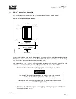
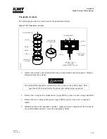
Plunger Button Sockets, Seals and Retainer Pins
1.
Remove the flat snap rings and plunger retainer pins on both ends of the piston.
2.
Inspect the snap rings and the pins for unusual wear or deformation. Clean and inspect the
pin holes for unusual wear, deformation or hole enlargement.
3.
Remove the plunger button o-ring and backup ring from each plunger socket. Take care
not to scratch or damage the seal groove surfaces.
4.
Clean and inspect the seal grooves for residue buildup or surface marks that could cause
seal leaks.
5.
Inspect the plunger button sockets for unusual wear.
NOTE
Due to the high contact force between the piston and the plunger, the plunger may
make an impression in the bottom of the socket. This compression mark or
indentation is normal.
6.
Apply FML-2 grease to new plunger button backup rings and o-rings. Install the rings in
the internal groove in the plunger socket. If the backup ring is not installed the plunger
can be forced out of the plunger socket.
7.
Install the plungers and the retainer pins, verifying that each pin moves freely without
excess side play in the pin holes.
8.
Install the flat snap ring over the pins.
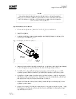
Internal Check Valves
It is not necessary to service the internal check valves unless a problem is suspected. If the check
valves or the internal passages in the piston require service, plunger button, seal and pin servicing
is also recommended. See Figure 9-21, Hydraulic Piston.
1.
Loosen the set screw and remove the check valves and o-rings. Clean the internal
passages.
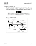
2.
Apply FML-2 grease to a new o-ring and install the new o-ring in the check valve
passage. Use a blunt, pencil-like instrument to position it in the bottom of the passage.
3.
Clean and install a new check valve with the chamfered end toward the o-ring.
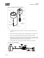
4.
Sparingly apply Loctite, threadlocker adhesive to the set screw. Thread the screw over the
check valve cartridge and tighten.
Содержание STREAMLINE SL-V SRP 100
Страница 1: ...MANUAL 20428408 R08 STREAMLINE SL V SRP 100 WATERJET INTENSIFIER OPERATION AND MAINTENANCE MANUAL ...
Страница 23: ......
Страница 25: ......
Страница 174: ...Section 12 Parts List 20428786 2 2008 Rev 05 12 5 Figure 12 1 SL V SRP 100 Intensifier Unit ...
Страница 176: ...Section 12 Parts List 20428786 2 2008 Rev 05 12 7 Figure 12 2 Intensifier Assembly ...
Страница 180: ...Section 12 Parts List 20428786 2 2008 Rev 05 12 11 Figure 12 5 Pneumatic Valve Actuator Assembly Normally Open ...
Страница 182: ...Section 12 Parts List 20428786 2 2008 Rev 05 12 13 Figure 12 6 Hydraulic Piston Assembly 05136684 ...
Страница 184: ...Section 12 Parts List 20428786 2 2008 Rev 05 12 15 Figure 12 7 High Pressure Piping ...
Страница 186: ...Section 12 Parts List 20428786 2 2008 Rev 05 12 17 Figure 12 8 Low Pressure Water Filter Assembly ...
Страница 188: ...Section 12 Parts List 20428786 2 2008 Rev 05 12 19 Figure 12 9 Hydraulic Power Package ...
Страница 190: ...Section 12 Parts List 20428786 2 2008 Rev 05 12 21 Figure 12 10 Motor Pump Assembly ...
Страница 192: ...Section 12 Parts List 20428786 2 2008 Rev 05 12 23 Figure 12 11 Hydraulic Manifold Assembly ...
Страница 194: ...Section 12 Parts List 20428786 2 2008 Rev 05 12 25 Figure 12 12 Hydraulic Hose Connections ...
Страница 196: ...Section 12 Parts List 20428786 2 2008 Rev 05 12 27 Figure 12 13 Reservoir Assembly ...
Страница 199: ...Section 12 Parts List 20428786 2 2008 Rev 05 12 30 Figure 12 14 Bulkhead Pipe Assembly ...
Страница 201: ...Section 12 Parts List 20428786 2 2008 Rev 05 12 32 Figure 12 15 Cover Assembly ...
Страница 203: ...Section 12 Parts List 20428786 2 2008 Rev 05 12 34 Figure 12 16 Electrical Assembly 200 208 50 60 ...
Страница 205: ...Section 12 Parts List 20428786 2 2008 Rev 05 12 36 Figure 12 17 Electrical Assembly 230 50 60 ...
Страница 207: ...Section 12 Parts List 20428786 2 2008 Rev 05 12 38 Figure 12 18 Electrical Assembly 380 415 50 60 ...
Страница 210: ...Section 12 Parts List 20428786 2 2008 Rev 05 12 41 Figure 12 19 Controls Subassembly 200 208 230 50 60 ...
Страница 213: ...Section 12 Parts List 20428786 2 2008 Rev 05 12 44 Figure 12 20 Controls Subassembly 380 415 50 60 ...
Страница 215: ...Section 12 Parts List 20428786 2 2008 Rev 05 12 46 Figure 12 21 Control Panel Configuration 200 208 50 60 ...
Страница 217: ...Section 12 Parts List 20428786 2 2008 Rev 05 12 48 Figure 12 22 Control Panel Configuration 230 50 60 ...
Страница 219: ...Section 12 Parts List 20428786 2 2008 Rev 05 12 50 Figure 12 23 Control Panel Configuration 380 415 50 60 ...
Страница 221: ...Section 12 Parts List 20428786 2 2008 Rev 05 12 52 Figure 12 24 Proportional Pressure Control 80075732 ...
Страница 223: ...Section 12 Parts List 20428786 2 2008 Rev 05 12 54 Figure 12 25 High Pressure Transducer ...
Страница 224: ......
Страница 225: ......
Страница 226: ......
Страница 227: ......
Страница 228: ......
Страница 229: ......
Страница 230: ......
Страница 231: ......
Страница 232: ......
Страница 233: ......
Страница 234: ......
Страница 235: ......
Страница 236: ......
Страница 237: ......
Страница 238: ......
Страница 239: ......


