


Section 9
High Pressure Water System
20428754
7-2007/Rev 03
9-2
9.2
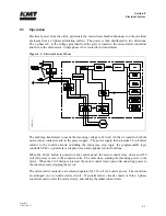
Operation
The directional control valve sends pressurized hydraulic oil to one side of the hydraulic cylinder.
The pressurized oil pushes against the piston, moving it in one direction until it activates the
proximity switch at the end of the stroke. The hydraulic flow is then sent to the opposite side of
the cylinder, and the piston reverses direction until it activates the proximity switch at the
opposite end of the stroke.
The green light on the proximity switch indicates there is power to the switch. The red light
illuminates when the switch is activated. The proximity switches are magnetically activated by
the presence of the metallic surface of the piston. When the switch is activated, it sends a signal
to the PLC to change the flow of the directional control valve and reverse direction.
As the pressurized oil pushes the piston in one direction, the plunger on that end extends and
pushes against the water in the high pressure cylinder, increasing the pressure up to 35,000 psi
(2,413 bar). When the piston reverses direction, the plunger retracts and the plunger in the
opposite cylinder extends to deliver the high pressure water.
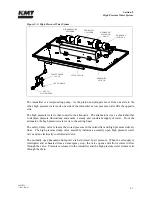
Figure 9-2: High Pressure Cylinder
Low pressure water is routed through the inlet water ports to the inlet passages in the sealing
heads. When the plunger retracts, the inlet check valve opens to allow water to fill the high
pressure cylinder. When the plunger extends to create high pressure water, the inlet valve closes
to seal the inlet passage and the discharge check valve opens to allow the high pressure water to
exit the cylinder. As the plunger retracts, the discharge check valve closes.
INLET
WATER
PASSAGE
DISCHARGE CHECK
VALVE
INLET
CHECK VALVE
SEALING HEAD
INLET
WATER PORT
OUTLET
WATER PASSAGE
HYDRAULIC
OIL IN
EXTENDED
PLUNGER
HYDRAULIC
PISTON
RETRACTED
PLUNGER
HIGH PRESSURE
CYLINDER
HYDRAULIC CYLINDER
STEM MOUNT
2
042
967
5
Содержание STREAMLINE SL-V SRP 100
Страница 1: ...MANUAL 20428408 R08 STREAMLINE SL V SRP 100 WATERJET INTENSIFIER OPERATION AND MAINTENANCE MANUAL ...
Страница 23: ......
Страница 25: ......
Страница 174: ...Section 12 Parts List 20428786 2 2008 Rev 05 12 5 Figure 12 1 SL V SRP 100 Intensifier Unit ...
Страница 176: ...Section 12 Parts List 20428786 2 2008 Rev 05 12 7 Figure 12 2 Intensifier Assembly ...
Страница 180: ...Section 12 Parts List 20428786 2 2008 Rev 05 12 11 Figure 12 5 Pneumatic Valve Actuator Assembly Normally Open ...
Страница 182: ...Section 12 Parts List 20428786 2 2008 Rev 05 12 13 Figure 12 6 Hydraulic Piston Assembly 05136684 ...
Страница 184: ...Section 12 Parts List 20428786 2 2008 Rev 05 12 15 Figure 12 7 High Pressure Piping ...
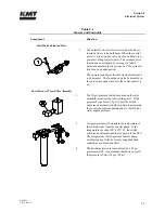
Страница 186: ...Section 12 Parts List 20428786 2 2008 Rev 05 12 17 Figure 12 8 Low Pressure Water Filter Assembly ...
Страница 188: ...Section 12 Parts List 20428786 2 2008 Rev 05 12 19 Figure 12 9 Hydraulic Power Package ...
Страница 190: ...Section 12 Parts List 20428786 2 2008 Rev 05 12 21 Figure 12 10 Motor Pump Assembly ...
Страница 192: ...Section 12 Parts List 20428786 2 2008 Rev 05 12 23 Figure 12 11 Hydraulic Manifold Assembly ...
Страница 194: ...Section 12 Parts List 20428786 2 2008 Rev 05 12 25 Figure 12 12 Hydraulic Hose Connections ...
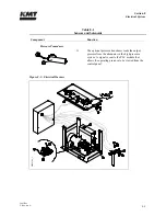
Страница 196: ...Section 12 Parts List 20428786 2 2008 Rev 05 12 27 Figure 12 13 Reservoir Assembly ...
Страница 199: ...Section 12 Parts List 20428786 2 2008 Rev 05 12 30 Figure 12 14 Bulkhead Pipe Assembly ...
Страница 201: ...Section 12 Parts List 20428786 2 2008 Rev 05 12 32 Figure 12 15 Cover Assembly ...
Страница 203: ...Section 12 Parts List 20428786 2 2008 Rev 05 12 34 Figure 12 16 Electrical Assembly 200 208 50 60 ...
Страница 205: ...Section 12 Parts List 20428786 2 2008 Rev 05 12 36 Figure 12 17 Electrical Assembly 230 50 60 ...
Страница 207: ...Section 12 Parts List 20428786 2 2008 Rev 05 12 38 Figure 12 18 Electrical Assembly 380 415 50 60 ...
Страница 210: ...Section 12 Parts List 20428786 2 2008 Rev 05 12 41 Figure 12 19 Controls Subassembly 200 208 230 50 60 ...
Страница 213: ...Section 12 Parts List 20428786 2 2008 Rev 05 12 44 Figure 12 20 Controls Subassembly 380 415 50 60 ...
Страница 215: ...Section 12 Parts List 20428786 2 2008 Rev 05 12 46 Figure 12 21 Control Panel Configuration 200 208 50 60 ...
Страница 217: ...Section 12 Parts List 20428786 2 2008 Rev 05 12 48 Figure 12 22 Control Panel Configuration 230 50 60 ...
Страница 219: ...Section 12 Parts List 20428786 2 2008 Rev 05 12 50 Figure 12 23 Control Panel Configuration 380 415 50 60 ...
Страница 221: ...Section 12 Parts List 20428786 2 2008 Rev 05 12 52 Figure 12 24 Proportional Pressure Control 80075732 ...
Страница 223: ...Section 12 Parts List 20428786 2 2008 Rev 05 12 54 Figure 12 25 High Pressure Transducer ...
Страница 224: ......
Страница 225: ......
Страница 226: ......
Страница 227: ......
Страница 228: ......
Страница 229: ......
Страница 230: ......
Страница 231: ......
Страница 232: ......
Страница 233: ......
Страница 234: ......
Страница 235: ......
Страница 236: ......
Страница 237: ......
Страница 238: ......
Страница 239: ......


