KMS MA-5 manual
Version 5.1
30
Target map
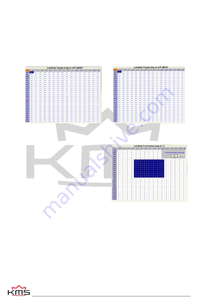
The A/F target map constitutes the same map structure used in the parameter maps for fuel/ignition.
The values input here constitute the target A/F ratio. The A/F ratio feedback or lambda control will
strive in each map position to control the A/F ratio towards this target value. This means that you can
drive with minimized consumption in the partial load range and fulfill the requirements of emission
laws. Towards a full load a richer A/F mixture can be automatically delivered, for the benefit of power
and cooling capacity of the engine. The adaptation of values in the target map works in the same way
as with the main maps (ignition/injection). When you input 0 in a frame, the A/F ratio feedback control
will not be active in the relevant range.
In the figure on the left side on the next page is a recommended target map shown for a N/A engine.
Next to that (on the right) is a recommended target map shown for a turbocharged engine.
Lambda target map for a N/A engine
Lambda target map for turbocharged engine
Correction map (Corr.Map1)
The A/F ratio feedback control corrects injection times so that the target values (specified in the target
value map) are attained. The percentage that the
A/F ratio feedback control must correct in order to
realize the target values is recorded in a correction
map. The values recorded in the correction map
can be selected and send as a correction
percentage to the injection map. Thus the map can
be adapted to minimize percentage of the A/F ratio
feedback control, which ensures optimum driving
characteristics. Make sure that the engine runs
smooth after the correction percentages are send to
the injection map. After the percentages have been
send to the injection map the entire correction map
needs to be reset to zero. Select the control box
‘clear lambda correction map’ and press ‘OK’ twice.
Allowed band for A/F ratio:
Correction percentages are only recorded in the correction map if the A/F ratio value (lambda value)
comes within a specific range of the desired value. This range can be adjusted in two settings. By
choosing level 2, the correction value will be recorded in the correction map if the A/F ratio feedback
value comes within 0.2 of the target (with level 1
≤ 0.1). With level 2, a 95% accurate correction map is
therefore created while a more precise one is created with level 1.
Recommended: Map the engine first on level 2. This way you can create the correction map faster.
Allowed band for correction map:
The 2 levels that can be selected here relate, in this case, to the deviation between actual and nominal
rpm and TPS (value set in map). Correction values are only recorded in the correction map when the
rpm and TPS comes within a specific range of the nominal value. With level 2, a 95% accurate
correction map is therefore created while a more precise one is created with level 1.
Recommended: Map the engine first on level 2. This way you can create the correction map faster.
Содержание 06.001-1
Страница 1: ...MA5 Manual V5 1 ...
Страница 60: ...KMS MA 5 manual Version 5 1 60 8 Appendix 1 Trigger pattern drawings ...
Страница 61: ...KMS MA 5 manual Version 5 1 61 ...
Страница 62: ...KMS MA 5 manual Version 5 1 62 ...
Страница 63: ...KMS MA 5 manual Version 5 1 63 ...


