Kipp & Zonen SOLYS Gear Drive Скачать руководство пользователя страница 1

SOLYS2

 • Sun Tracker

SOLYS Gear Drive

  • Sun Tracker

Instruction Manual

Содержание SOLYS Gear Drive

Страница 1: ...SOLYS2 Sun Tracker SOLYS Gear Drive Sun Tracker Instruction Manual...

Страница 2: ...2...

Страница 3: ...in the conditions of delivery is valid only if the product has been installed and used according to the instructions supplied by Kipp Zonen Kipp Zonen shall in no event be liable for incidental or con...

Страница 4: ...4...

Страница 5: ...CEO Kipp Zonen B V EMC Emissions EMC Immunity Electrical safety Environmental Affairs EN 61326 2 1 2013 and EN 61326 2 3 2013 EN 61326 2 1 2013 and EN 61326 2 3 2013 EN 61010 1 2010 EN 50581 2012 EMC...

Страница 6: ...6...

Страница 7: ...5 Side mounting plate Middleton SPO2 Sun Photometer 3 6 Side mounting plate Eppley A HF Absolute Cavity Pyrheliometer 3 7 Side mounting plate Eppley NIP second pyrheliometer mount 3 8 Side mounting p...

Страница 8: ...ents 6 4 RS 485 connection 7 Software overview 8 Firmware 9 Trouble shooting 9 1 Problem check list 9 2 FAQ Appendices A Serial communication protocol introduction A 1 Firmware release A 2 Instrument...

Страница 9: ...ts D 4 6 Show serial interface number of data bits D 4 7 Set serial interface number of stop bits D 4 8 Show serial interface number of stopbits D 4 9 Clear serial interface con guration D 5 Miscellan...

Страница 10: ...10...

Страница 11: ...platform used to point specialized instruments at the sun s movement across the sky It is fully automatic and does not require a computer or software for installation or operation The SOLYS does prov...

Страница 12: ...tracking for mid SOLYS2 25kg or high payload SOLYS Gear Drive 80 kg Its accuracy is excellent for both solar monitoring or meteorological applications where reliability and accurate tracking is requir...

Страница 13: ...position of the sun sensor 2 1 2 Site preparation A site must be prepared before installing a SOLYS sun tracker The following points need to checked The site where the SOLYS sun tracker is placed mus...

Страница 14: ...important to consider the following points before during the installation of a SOLYS Verify that all cabling is routed properly to prevent cables from catching on any fasteners supports the SOLYS or...

Страница 15: ...g holes to fix the SOLYS to this base The SOLYS Tripod Floor Stand has a Kipp Zonen logo This logo needs to be pointed to the East Mount options and instruments before final leveling and alignment of...

Страница 16: ...ty Tripod Floor Stand one of the 3 legs needs to point East It is required to perform the leveling and alignment during installation of the SOLYS options and instruments first before actually tighten...

Страница 17: ...Kipp Zonen logo on the tripod must point to the East when mounting the SOLYS Ideally the bolts should be in the middle of the slots when the tripod is mounted to the SOLYS This allows fine tuning the...

Страница 18: ...om flange When installed an initial Azimuth orientation due East with the help of a compass will do When the SOLYS is powered later on exact positioning can be performed when sun is available Figure 2...

Страница 19: ...justed using a 13 mm wrench The accuracy of the SOLYS is within 0 1 when the bubble is within the circle During installation we recommend to keep the bubble inside the ring However if the bubble is ha...

Страница 20: ...rnal heater Important operating temperature The SOLYS has a lower operating temperature range of 20 C when operating on 24 VDC When AC power is applied the standard built in heater will be used The us...

Страница 21: ...lied voltage to be out of specifications Both the AC and DC connectors are suitable for cable diameters between 6 and 12 mm For 6 to 9 mm and 9 to 12 mm different sealing rings are used The AC connect...

Страница 22: ...d outdoors specify that A power isolator switch or circuit breaker must be included in the cable installation The isolator switch or circuit breaker must be in close proximity to the equipment and wit...

Страница 23: ...to its home position and starts its active tracking mode with full power consumption If no other power is available even a few days without sun should be covered by the back up battery Two 12 V backup...

Страница 24: ...but only operates on AC power In cold conditions when the power LED is red and the SOLYS is AC powered it can take a while before the internal heater has warmed the interior above 20 C The Status LED...

Страница 25: ...changes than also re align the sun sensor again see chapter 3 11 1 Input voltage can be 24 VDC or 100 to 240 VAC if both are present AC power will be used When running on AC power and the internal te...

Страница 26: ...see illustration 4 5 The vertical adjustment of the side mounting plate is a factory setting which should be OK If the side mounting plates have been loosened or removed adjust the zenith position as...

Страница 27: ...plate is used to mount the shading drive arm without instrument mounting clamps this drive arm should be aligned with the first one before fixating the screws on the axis The SOLYS can handle payload...

Страница 28: ...gram Recheck the alignment using the two alignment target holes on the pyrheliometer The pyrheliometer has its own instruction sheet and manual for detailed information In the instruction sheet you wi...

Страница 29: ...g plate that is included 1x with the SOLYS This information is required to create mounting materials for optional components or instruments This mounting plate is intended for loads up to 25 kg For th...

Страница 30: ...eliometer on side mounting plate The SOLYS has only one side mounting plate present as default When ordering a PMO 6 mounting kit please check if you need an additional side mounting plate Side mounti...

Страница 31: ...n of Middleton SPO2 sun photometer adapter on side mounting plate The SOLYS has only one side mounting plate present as default When ordering a SPO2 mounting kit please check if you need an additional...

Страница 32: ...avity pyrheliometer on side mounting plate The SOLYS has only one side mounting plate present as default When ordering a HF AHF mounting kit please check if you need an additional side mounting plate...

Страница 33: ...ley NIP or second pyrheliometer on top of the existing mounting clamp Side Mounting Plate with two standard Pyrheliometer Mounting Clamps Pyrheliometer Clamp 2x Pyrheliometer Clamp 2x Second Pyrheliom...

Страница 34: ...ing plate The SOLYS has only one side mounting plate present as default When ordering a PGS 100 mounting kit please check if you need an additional side mounting plate Side mounting plate M4x20 at hea...

Страница 35: ...6x CHP1 SHP1 required extra parts 3x 0367710 3x 0367717 brackets When the large side mounting plate is used on both sides the above number can be double or combinations can be made The individual moun...

Страница 36: ...extension tube The tube can be mounted on the Heavy Duty Tripod Floor Stand Mounting the height extension tube on the small Tripod Floor Stand is not possible An adapter plate is included to the mount...

Страница 37: ...photo diode sensor fitted within a weather resistant enclosure with SOLYS mounting hardware The sun sensor is standard on the SOLYS Gear Drive On the SOLYS2 it is optional Figure 3 11 Preparing the mo...

Страница 38: ...Figure 3 12 Mounting the sun sensor M5 locking nut 3x Shoulder washer 6x Compression spring 3x Sun Sensor 38...

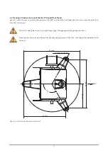
Страница 39: ...Figure 3 13 Adjustment of the sun sensor 21 0 5 mm 3x 39...

Страница 40: ...e alignment targets of the two mounting brackets can be used Both brackets have a hole and the light beam falling through the first hole should make a circle just around the second hole The informatio...

Страница 41: ...ide a mechanical assembly to ensure accurate shading during normal solar tracking operations Listed below is a recommended sequence of the assembly First install the lower pivot bar on the underside o...

Страница 42: ...with its two screws after aligning the two shading drive arms see figure 3 16 Now tighten the T bar locking nuts until most of the clearance is gone between the arms and shoulder washers Do not tight...

Страница 43: ...the nylon washers and locking nut Only tighten the locking nut to minimize clearances ensure free rotational movement Figure 3 17 Mounting of the top part of the shading support arm Shoulder washer 2x...

Страница 44: ...Figure 3 18 Mounting of the lower part of the shading support arm M5x35 cap screw 1x Shoulder washer 3x Flat nylon washer 1x Locking nut M5 1x 44...

Страница 45: ...3 13 Top mounting plate assembly The next figure indicates how to mount the top mounting plate Figure 3 19 Mounting the top mounting plate M5x12 flat head screw 4x Top mounting plate 45...

Страница 46: ...es for mounting up to three Kipp Zonen radiometers Figure 3 20 Kipp Zonen radiometers mounting holes without ventilation unit Figure 3 21 Kipp Zonen radiometers mounting holes without ventilation unit...

Страница 47: ...top mounting plate the setup for the shadow balls and a total view for mounting the UVS instruments on top of the SOLYS Figure 3 22 Location of the holes inside the top mounting plate Figure 3 23 The...

Страница 48: ...up to three Kipp Zonen ventilation units Figure 3 24 Kipp Zonen radiometers mounting holes with ventilation unit Figure 3 25 Kipp Zonen pyranometer with ventilation unit diagram Mounting holes for CVF...

Страница 49: ...holes required to mount an Eppley radiometer to the top mounting plate Figure 3 26 Mounting of ventilated Eppley instruments on the top mounting plate Figure 3 27 Mounting of Eppley radiometers on th...

Страница 50: ...03 5 324 5 7 0 2 6 0 2 2 179 4 224 3 100 4 145 9 4 2 7 324 5 5 21 4 224 6 67 9 324 5 7 70 6 224 8 171 145 9 9 271 4 224 10 274 1 324 5 11 320 6 224 12 339 3 324 5 13 442 4 145 9 14 521 4 224 15 545 5...

Страница 51: ...holes Fine tuning of the ball rods must be done later in the installation after the verification of leveling procedure Do not over tighten the locking screws It would make fine tuning adjust ments di...

Страница 52: ...for Kipp Zonen radiometers without ventilation unit Figure 3 31 Shading ball rods for Kipp Zonen radiometers with ventilation unit It s important for the detector of the instrument to be fully shaded...

Страница 53: ...unting for measuring tilted tracking global radiation Figure 3 32 Tilted pyranometer mounting kit M4x20 flat head screw 2x Side Mounting Plate Pyranometer remove 3 feet Spacer 3x Adapter M6x20 cap scr...

Страница 54: ...pp Zonen radiometer Figure 3 33 Small top mounting plate 54 7 8 6 5 2 4 1 3 336 0 5 106 0 5 15 X Y 0 0 342 15 R 2x X 0 2 Y 0 2 SIZE 1 7 5 24 7 0 2 6 0 2 x 11 0 2 x 90 6 0 2 2 7 5 124 3 334 5 24 4 334...

Страница 55: ...he required heating power of the SOLYS Gear Drive The SOLYS Gear Drive internal heater is switched off when the internal temperature is above 5 C The cold cover can be mounted after the installation o...

Страница 56: ...C To protect the SOLYS in this case for direct radiation a sun shield is available This allows for use in temperatures up to 60 C The sun shield also protects the bubble level for direct radiation The...

Страница 57: ...the proper cable length as indicated below so that the SOLYS can move freely throughout the entire year As a security check the SOLYS will make a 540 degree rotation lap when powering up Figure 3 36...

Страница 58: ...tools for the shading assembly The kit includes the 6 screws to position the shading ball rods Not including the 3 screws for mounting the SOLYS on the Tripod Floor Stand 3 25 2 Screw kit for pyrheli...

Страница 59: ...normal operation The Ethernet connection has a loose gray cap Both power connections and the sun sensor have attached caps that should be closed when not in use 4 1 Ethernet connection 1 Download and...

Страница 60: ...ugh cable gland 5 Apply self fusing tape Locate tape as shown and mold around Ethernet Cable about 2 turns Remove plastic liner of self fusing tape supplied 60 mm Remove rubber cover Remove the releas...

Страница 61: ...6 Insert the Ethernet cable Contacts on this side 61...

Страница 62: ...or is properly inserted the upper part of the Ethernet cable gland can be screwed in the housing Push the cable upwards so the connector remains in place Please note that only the lower part nut of th...

Страница 63: ...mmunication with the SOLYS is established via its network interface The Ethernet connection is suitable for permanent use however the SOLYS is not protected by an internal firewall Therefore the netwo...

Страница 64: ...alled SOLYSMonitor It allows you to check and log the status and control the communication parameters Up to 10 SOLYS sun trackers can be connected and monitored SOLYSMonitor includes the following fun...

Страница 65: ...port for this convert er from the pull down menu The other communication parameters are set correct and are the default values By clicking the box Add SOLYS this SOLYS will be connected and apear in t...

Страница 66: ...n connecting directly to your PC a so called cross cable has to be used By clicking the pull down menu in the selection box the program starts searching on the network for all available SOLYS s You ca...

Страница 67: ...tored and logged at the same time Add SOLYS System Tracking Status Instrument Status Configuration Browser Remove SOLYS System Solar angle azimuth Solar angle zenith COM10 Axis angle azimuth Axis angl...

Страница 68: ...flags COM10 Azimuth motor status Azimuth motor flags Zenith motor status Zenith motor flags Using last received GPS latitude longidtude and altitude System clock stratum synchronized Sun sensor intens...

Страница 69: ...ions this file contains the following information for every second 2015 02 26 11 29 42 429 computer logging date and time status 1 Message type SolysGD140003 SOLYS network name 2015 02 26 SOLYS date 1...

Страница 70: ...munication parameters Serial Break reset the SOLYS to default comm Parameters after 5 seconds switch to stored configuration Reset Track restart sun tracking Warm Reset restart the SOLYS Cold Reset se...

Страница 71: ...15001 Number of connections 10 When the server has 10 socket connections and receives a new connection request it will accept the new connection and drop the oldest connection The oldest connection i...

Страница 72: ...e download the following LOG files From the SOLYS User Interface select Logging and then select the files 1 Data Archive 2 Sun Log csv gz new 3 Save these file to the computer Send the saved files to...

Страница 73: ...aximum operating acceleration for the azimuth and zenith motors Startup time BE To retrieve the time at which the most recent session reset began Checkout time CH With this function you can actually s...

Страница 74: ...he configuration due to GPS altitude changes 1 updates enabled 0 updates disabled Location and pressure LL To retrieve or set the latitude longitude and nominal atmospheric pressure recorded for the s...

Страница 75: ...C To retrieve or set the scaling factor for each sun sensor quadrant along with the nominal scaling of the sensor Serial number SE To retrieve the serial number of the SOLYS Sun intensity SI Retrieves...

Страница 76: ...rieve or set the range for the instrument azimuth and zenith 6 2 Serial interface This chapter describes the serial communication protocol between the SOLYS and the computer or other connected device...

Страница 77: ...applications to the TCP port This may lead to unexpected behavior 4 5 1 Error codes If an unrecognized command or a command with missing or incorrect parameters is received the tracker will respond NO...

Страница 78: ...78...

Страница 79: ...on of all cables and connectors Check drying cartridges for mounted radiometers Check if bubble level s still within range Check the pyrheliometer sun sensor alignment The SOLYS itself does not need a...

Страница 80: ...80...

Страница 81: ...AC power DC power Plugs for AC and DC supplied Ethernet interface RJ 45 DHCP client Zeroconf Manual network configuration ICMP type 8 and 17 mDNS UDP port 5353 Web interface TCP port 80 NTP service UD...

Страница 82: ...r For Middleton SP02 or SP01 L sun photometer For PGS 100 Sun Photometer For Eppley HF AHF absolute cavity pyrheliometer For 1 Eppley NIP pyrheliometer either as a second pyrheliometer or directly to...

Страница 83: ...ity Standard Via Ethernet port Standard Michalsky algorithm 1988 Firmware update possible Flash memory Via Ethernet port Maintenance No scheduled maintenance required Annual inspection recommended Aut...

Страница 84: ...6 3 Height specifications SOLYS including instruments The next illustration displays the actual height of the instruments 515 mm 659 mm 684 mm 591 mm 84...

Страница 85: ...e serial protocol commands and messages are described in appendix A to E Both the RS 485 and the sun sensor have a 8 pin connector Identification of the port is on the labels next to the connectors Ex...

Страница 86: ...86...

Страница 87: ...the equation of time the correction is also applied into this algorithm 7 Software overview Apache httpd 2 2 8 Apache License 2 0 Avahi avahi 0 6 17 LGPL 2 1 BusyBox busybox 1 1 3 GPL 2 Expat XML par...

Страница 88: ...88...

Страница 89: ...prevent any unwanted situations in the future To download the latest firmware update please check the SOLYS webpage under downloads 8 1 Firmware upgrade Step 1 4 Connecting computer Chapter 4 3 has th...

Страница 90: ...ss the Upload button and wait till the upload is completed The upload is completed when the message Reboot tracker to apply update appears Select Reboot Do not power off the SOLYS it may render it unu...

Страница 91: ...d options Problem description Log files see chapter 4 3 If you cannot solve the problem by the tips on the next pages email the problem description to support kippzonen com call us at 31 15 2755 210 o...

Страница 92: ...PS position is received The SOLYS will now rotate to the sun position 7 Rotate the SOLYS on its tripod adjust azimuth until the alignment target from the pyrheliometer or pyrheliometer bracket points...

Страница 93: ...instrument Note the instrument will regularly send status messages to the host so the host is kept up to date regarding the current status of the instrument The interval of the status messages is 1 s...

Страница 94: ...and requests B 2 Client server protocol The instrument provides the information and will send a response on every command from the HOST Every request from the HOST is acknowledged by 0 1 or more resp...

Страница 95: ...ubcommand1 subcommand2 LF or dot command space param1 value1 param2 value2 LF Optional parameters and subcommands are placed between parenthesis Examples Request reset track LF Response ok LF Request...

Страница 96: ...ay set ser0baudrate D 4 1 Set the serial interface baudrate set ser0parity D 4 3 Set the serial interface parity set ser0databits D 4 5 Set the serial interface number of databits set ser0stopbits D 4...

Страница 97: ...vert the serial interface con guration to defaults clear track D 5 1 Revert the suntracking con guration to defaults clear all D 5 2 Issue clear account ip0 ser0 and track C 2 5 Overview command reset...

Страница 98: ...ent operational mode Description The command set opermode mode will set the instrument operational mode Argument 1 Description The instrument operational mode Type Text string Range normal maintenance...

Страница 99: ...ked out Under normal circumstances the IPv4 con guration should be done using the web interface D 3 1 Set IP address method Description The command set ip0method method will set the IP address method...

Страница 100: ...sponse ok D 3 4 Show IP address Description The command show address will show the con gured IP address Argument none Example Request show ip0address Response ip0address 10 1 2 100 ok D 3 5 Set IP net...

Страница 101: ...The command set ip0gateway gateway will set the IP gateway Argument 1 Description IP gateway Type 4 octet text string Range 0 0 0 0 to 255 255 255 255 Default 255 255 255 0 Example Request set ip0gate...

Страница 102: ...appens a few seconds later possibly while sending a status message D 4 1 Set serial interface baud rate Description The command set ser0baudrate rate will set the baud rate Argument 1 Description baud...

Страница 103: ...how serial interface parity Description The command show ser0parity will show the con gured parity Argument none Example Request show ser0parity Response ser0parity even ok D 4 5 Set serial interface...

Страница 104: ...ber of stop bits Description The command set ser0stopbits bits will set the number of stop bits Argument 1 Description number of stop bits Type integer Range 1 or 2 Default value 1 Example Request set...

Страница 105: ...to defaults The instrument will reset as a result of this command This command has the same effect as the reset cold command see paragraph 0 Argument none Example Request clear track Response ok D 5 2...

Страница 106: ...mputer keeps running Argument none Example Request reset track Response ok D 6 2 Warm reset Description The command reset warm will restart the instrument Argument none Example Request reset warm Resp...

Страница 107: ...essage Pos Field name Description 0 Message type 0 1 Hostname Instrument hostname 2 Date Current date YYY MM DD 3 Time Current time HH MM SS 4 Solar angle azimuth Calculated solar angles in degrees No...

Страница 108: ...tatus See paragraph E 2 5 14 Zenith motor status 15 Checksum CRC 16 reverse bit order with seed of 0 and XOR polynomial of 0xA001 The checksum is calculated over all characters till not including the...

Страница 109: ...een Green 0x022 using last received GPS latitude longitude and altitude system clock stratum 3 no sunsensor Suntracking Green Green Off 0x122 using last received GPS latitude longitude and altitude sy...

Страница 110: ...sors 23 resetting globally nding ref sensors 24 resetting accurately nding ref sensors 25 resetting accepting reset 26 resetting waiting in ref and moving over travel range 27 resetting preparing for...

Страница 111: ...moving in response to commands on path 10 nding sun 11 following sun 240 encoder disabled 241 moving due to encoder failure 242 encoder failure 243 movement done 244 moving over travel range 245 waiti...

Страница 112: ......

Отзывы: