


D3DP 3xx/x
Connections and wiring
Project engineering manual V1.00
46
© KEBA
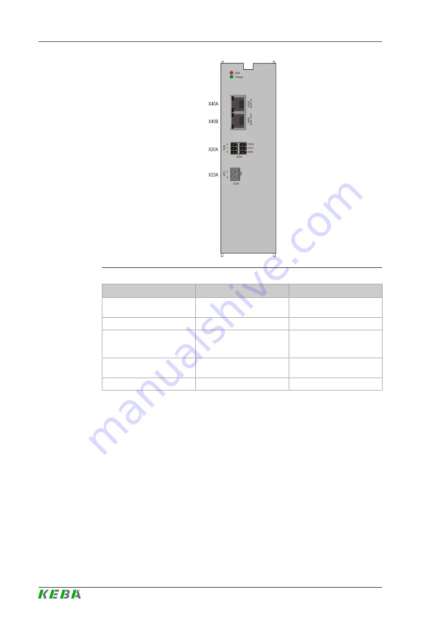
Illustration 623: Layout supply module front panel
Abbreviation
Designation
Details
LED red (ERR)
Error status supply modulel
(Flashing code)
See
LED green (Voltage)
Status mains supply present
See
X40A/ X40B
Communication with con
troller and axis module
(EtherCAT)
See
X20A / State
Relay contact (RO0) digital
outputs (TDO0, TDO1)
See
X23A / REL Output
Relay contact (RO1)
See
6.5
Specification of EtherCAT interface
The EtherCAT field bus interface X40A is typically used for the connection of
the control module D3DU 3xx/x or another EtherCATcompliant control
module with EtherCAT master.
It can also be used as a service and diagnostics interface. However, it is
then only suitable for the connection of a PC for commissioning, service and
diagnostics using the software DriveManager.
Technical specification:
●
Transfer rate 10/100 MBits/s BASET
●
Transfer profile IEEE802.3 compliant
Содержание D3DP 3 Series
Страница 1: ...D3 DP 3xx x Supply module Project engineering manual V 1 00 Translation of original manual ...
Страница 4: ...D3 DP 3xx x Project engineering manual V1 00 4 KEBA ...
Страница 8: ...D3 DP 3xx x Table of Contents Project engineering manual V1 00 8 KEBA ...
Страница 74: ...D3 DP 3xx x Declaration of conformity Project engineering manual V1 00 74 KEBA 14 Declaration of conformity ...
Страница 75: ...D3 DP 3xx x Declaration of conformity Project engineering manual V1 00 75 KEBA ...
Страница 76: ...D3 DP 3xx x Declaration of conformity Project engineering manual V1 00 76 KEBA ...
Страница 77: ...D3 DP 3xx x Declaration of conformity Project engineering manual V1 00 77 KEBA ...
Страница 80: ...D3 DP 3xx x Glossary Project engineering manual V1 00 80 KEBA Glossary ...
Страница 81: ...D3 DP 3xx x Index Project engineering manual V1 00 81 KEBA Index ...
Страница 82: ...D3 DP 3xx x Index Project engineering manual V1 00 82 KEBA ...


