44
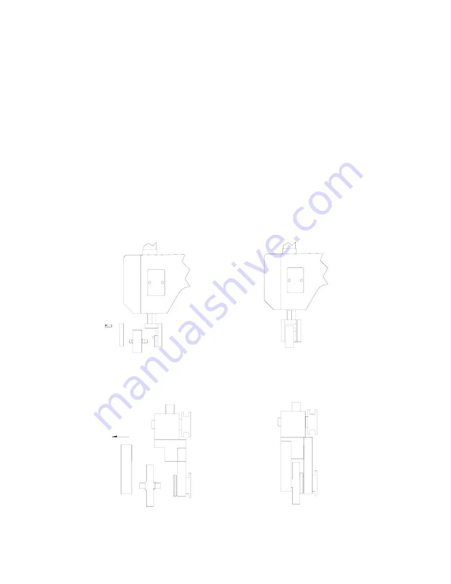
7.5 Installation and Replace the Working Roller
A.
Tread down the left side foot switch to lift up
the sealing roller bracket.
B.
Remove the outer W.R. bracket by loosing the 2 set screws with the T-type
hexagon wrench supplied. Then take out the roller. When installation the
desired working roller, be sure that the hole in the working roller fits into the
pin on the pulley wheel gear. And the long shaft innermost towards the inner
side.
C.
Using 2 screws install the outer working roller bracket, then tread down the left
side foot switch again to lower down the roller bracket.
D.
Feed the workpiece in between O.P.P. strip and paper strip and run the machine.
E.
Adjustment: If the workpiece is not uniform across the width (i.e. more
pressure is applied one side than the other), then adjust the height of outer
bracket
(
loosen the screws
)
and raise or lower the outer bracket to suit
(retighten the screws) the retest.
(KS-72, KS-85 Fig. 1) (KS-72, KS-85 Fig. 2)
(KS-2010, KS-3010 Fig. 1) (KS-2010, KS-3010 Fig. 2)
Содержание KS-2010
Страница 12: ...11 ...
Страница 13: ...12 ...
Страница 22: ...21 ...
Страница 23: ...22 ...
Страница 31: ...30 6 4 Wiring Diagram A MAIN WIRING DIAGRAM A 1 KS 72 ...
Страница 32: ...31 A 2 KS 85 ...
Страница 38: ...37 FUSE FUSE B GENERATOR CIRCUIT DIAGRAM KS 72 KS 85 KS 2010 KS 3010 ...


