background image

 Commissioning 


Ref. no. 2103 REG ES  

Page 10


of 44


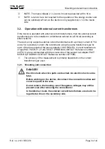
3.2.2. Operational 

instructions 


During operation with open secondary sides, high voltages can occur on 
current transformers. For this reason, the current transformers must always be 
connected to the inputs E1, E2, E3, before reconnecting the primary circuit.  


The connection of the current transformers to the inputs E1, E2 and E3 of the 
energy detector 2103 REG ES prevents such surge voltages.  


The connection of the secondary sides of the current transformers with the 
input voltage means that the current transformers and their connections have 
a 230 V voltage potential. 


The secondary sides of the current transformers are therefore live parts and 
must be covered, so that cannot be touched after installation. 


4. Commissioning 


DANGER! 

Electric shock when live parts are touched. An electric shock can be 
fatal. 
Before working on the device, disconnect the connection cables and 
cover live parts in the area. 
Do not remove the housing cover! Dangerous voltages may still be 
present even after removing the connections! 
In transformer mode, the external current transformers are also to be 
regarded as live on the secondary side. 

After setting the physical address, loading the application by means of ETS and 
connecting to the mains voltage, the energy counter is ready for operation. 
The Power LED lights up continuously if the energy counter is in operation and the 
energy saving mode is not active. Channel LEDs E1, E2 and E3 indicate the 
measurement of an energy amount of 1/6400 kWh at the respective channel by 
lighting up briefly. 
If the Power saving mode is activated, the Power LED goes out and no energy is 
counted. 


Содержание 2103 REG ES

Страница 1: ... ES ALBRECHT JUNG GMBH CO KG Volmestraße 1 58579 Schalksmühle Telephone 49 0 2355 806 0 Telefax 49 0 2355 806 204 kundencenter jung de https www jung de en Service Center Kupferstr 17 19 Date of the documentation 06 2020 44532 Lünen Germany ...

Страница 2: ...afety instructions 6 3 Mounting and electrical connection 7 3 1 Operation without external current transformer 7 3 1 1 Mounting and connection 7 3 2 Operation with external current transformers 8 3 2 1 Mounting and connection 8 3 2 2 Operational instructions 10 4 Commissioning 10 5 Application 11 5 1 Specification 11 5 2 Overview 12 5 2 1 Measured values 12 5 2 2 Energy counter 13 5 2 3 Rate count...

Страница 3: ...rated monitoring functions peak loads can be detected reported and avoided by means of additional measures All information limiting values and measured values are accessible via KNX telegrams The device is suitable both for direct current measurement and for current measurement with external current transformers The connection of external current transformers allows the measurement of greater curr...

Страница 4: ...its Installation position Any preferably top output terminals Minimum distances None Fastening type Snapping onto top hat rails in closed housing e g small distributors etc Connection terminals for mains power supply and inputs Connection type Screw terminal Single wire 0 5 4 mm Stranded without ferrule 0 5 4 mm Stranded with ferrule 0 5 2 5 mm Connection torque max 0 8 Nm KNX supply KNX Medium TP...

Страница 5: ...ncy Active power signed Reactive power signed Active energy signed Measuring accuracy 1 Without external current transformer Active consumption 2 mA 10 mA 5 150 mW Active consumption 10 mA 200 mA 2 Active consumption 200 mA 16 A 1 With external current transformers Active consumption 30 mA 150 mA 10 2 W Active consumption 150 mA 3 A 3 Active consumption 3 A 75 A 2 Pulse LED 6400 kWh Pulse duration...

Страница 6: ... the leads rated current 16 A When using external current transformers comply with the documentation of the current transformers The external current transformers are also to be regarded as live on the secondary side Danger of electric shock During installation and cable routing comply with the regulations and standards which apply for SELV circuits During installation ensure sufficient insulation...

Страница 7: ...tions 3 1 Operation without external current transformer 3 1 1 Mounting and connection Connection diagram for direct current measurement Snap the device onto the DIN rail The terminals for the mains should be located at the top Connect the mains load and bus terminal as shown in Fig 2 In so doing the neutral conductor must be connected to the device On removal the neutral conductor must be disconn...

Страница 8: ...t We recommend using the same transformer type for each of the three inputs of the energy detector 2103 REG ES Current transformers of type PACT MCR V1 21 44 75 5A 1 PHOENIX CONTACT Reference number 2277611 are recommended with the accessories of the support rail adapter PACT MCR RA PHOENIX CONTACT Reference number 2277598 The accuracy of the measurement is primarily dependent on the current trans...

Страница 9: ...ad must always be inserted between the output and the neutral conductor symbol The output and neutral conductor may not be connected without a load The mains voltage infeed lines to the primary sides of the current transformers must be protected according to the primary rated current and the current rating of the cable with F1 F2 F3 fuses max 75 A The secondary sides of the current transformers ar...

Страница 10: ...touched after installation 4 Commissioning DANGER Electric shock when live parts are touched An electric shock can be fatal Before working on the device disconnect the connection cables and cover live parts in the area Do not remove the housing cover Dangerous voltages may still be present even after removing the connections In transformer mode the external current transformers are also to be rega...

Страница 11: ...oftware onwards You can determine the version level using the Device information ETS function Fig 4 ETS Device information If the device software is an older version then an update to Version 0 2 or higher is required 5 1 Specification Bus coupling unit E981 03 KNX type class 3b Number of communication objects 125 Configuration S Mode without Plug In ETS Version 3 0d or higher Patch A ...

Страница 12: ...power and reactive power are added up across all channels as three phase current variables and also the mains frequency is provided According to the configuration the measured values will be transmitted to the KNX bus either cyclically and or on a change or explicit request For some variables a telegram is transmitted if a limit value is fallen below or exceeded The measured values are calculated ...

Страница 13: ...f the active power Thus a counter only counts when the basic active power does not equal zero The counting is balanced i e if the active power is positive then the counter increases If it is negative then it decreases A negative active power corresponds to a reverse output flow The balanced counting means that the counter level can contain both positive and negative values Fig 6 shows the relation...

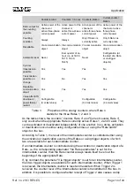
Страница 14: ... Rate n stands for the three Rates 1 2 and 3 As the table shows the counters Counter Rate n and Current counter Rate n only count when the appropriate Rate is currently active Rates 1 2 and 3 exist They can be activated or deactivated independently of one another In so doing activation or deactivation occurs either using configurable times or using the Rate switch object on the bus According to Ta...

Страница 15: ...s the current cost level in Euro cents The following figure shows the three cost counters in relation to the basic measurand and the three phase current counters Calculation of the cost counters As Fig 7 shows all three Rate related three phase current counters are derived from the measurand of the active three phase current power This is counted in the time during which the appropriate Rate is ac...

Страница 16: ...ounter Rate 2 Three phase current counter Rate 3 Resettable Only synchronous to three phase current counter Rate 1 via communication object Only synchronous to three phase current counter Rate 2 via communication object Only synchronous to three phase current counter Rate 3 via communication object Automatic reset Never Never Never Cyclical transmission possible Yes Yes Yes Transmission possible o...

Страница 17: ...le value in order to request the current time from a KNX clock Object Name Object function Type DPT Flag 3 General In Use 1 bit 1 xxx C T Description This object can be transmitted cyclically with a configurable value and represents a status message for the operation of the energy counter Object Name Object function Type DPT Flag 4 Gen measure Request measured values 1 bit 1 xxx C W Description On...

Страница 18: ...ich if over or undershot a monitoring telegram can be transmitted can be changed using this object The new limit value is stored permanently or in the volatile memory according to the configuration Object Name Object function Type DPT Flag 10 16 22 26 Chn LV exceed below Effective power 1 bit 1 xxx C T Description If the limit value for the effective power is over or undershot a monitoring telegra...

Страница 19: ...hour of the hour counter of the channel in Wh The counter levels C1 EC Object 31 C2 EC Object 54 and C3 EC Object 77 pertain to the alternating current counters which only count the energy in one channel or one phase By contrast the counter level 3 phase values EC Object 100 counts the total energy of all three channels or all three phases Object Name Object function Type DPT Flag 32 55 78 101 Chn...

Страница 20: ... Description The intermediate counter level of the channel for Rate 1 is reset on receiving this object The value of the object is irrelevant here Object Name Object function Type DPT Flag 38 61 84 107 Chn EC Rate 1 Trigger 1 Curr count reading 1 bit 1 017 C W Description If appropriate configured the intermediate counter of the channel for Rate 1 is reset and started on receiving this object The ...

Страница 21: ...n EC Rate 2 Trigger 1 Curr count reading 1 bit 1 017 C W Description If appropriate configured the intermediate counter of the channel for Rate 2 is reset and started on receiving this object The value of the object is irrelevant here Object Name Object function Type DPT Flag 45 68 91 114 Chn EC Rate 2 Trigger 2 Curr count reading 1 bit 1 017 C W Description If appropriately configured the interme...

Страница 22: ...urr count reading 1 bit 1 017 C W Description If appropriately configured the intermediate counter level of the channel for Rate 3 is transmitted on receiving this object The intermediate counter is optionally stopped The value of the object is irrelevant here Object Name Object function Type DPT Flag 121 Rate Change rate 1 bytes 5 xxx CRWT Description With this object it is possible to specify wh...

Страница 23: ...ger value is interpreted in 0 1 ct kWh Object Name Object function Type DPT Flag 126 Rate Rate 2 Price 2 bytes 7 xxx C WT Description The object can be used to specify a price for Rate 2 via the bus If a telegram is transmitted to this object then the price configured by the ETS is overwritten However the price of the Rate will be set back to the price configured by the ETS on the next ETS downloa...

Страница 24: ...it is possible to set whether an object for requesting the time is transmitted after a bus voltage return Value of communication object Time request 0 1 The object for requesting the time has the value specified here Send object In use 0 65535 A status message for the operation of the energy counter can be transmitted cyclically Setting of the seconds of the cycle time or switch off of this functi...

Страница 25: ...2 Yes No Access to the measured and power values of Channel 2 can be enabled here Release Channel 3 Yes No Access to the measured and power values of Channel 3 can be enabled here Release 3 phase values Yes No Access to the measured and power values of the three phase current variables can be enabled here Release frequency measurement Yes No Access to the measured frequency can be enabled here Sen...

Страница 26: ...t which the measured current intensity is transmitted or switch off of this function with the value 0 Send effective power on change W 0 4240 The effective power measured on Channel 1 can be transmitted on changes Setting of the effective power change at which the measured effective power is transmitted or switch off of this function with the value 0 Telegram on limit value Effective power Yes No ...

Страница 27: ...easured values of Channel 2 can be transmitted cyclically Voltage rms Current rms Effective power Reactive power Setting of the seconds of the cycle time or switch off of this function with the value 0 Send voltage on change V 0 265 The voltage measured on Channel 2 can be transmitted on changes Setting of the voltage change at which the measured voltage is transmitted or switch off of this functi...

Страница 28: ...tive power measured on Channel 2 On overshooting the actual limit value is Limit value hysteresis and on undershooting Limit value hysteresis Specification of the hysteresis for the effective power measured on Channel 2 Send reactive power on change W 0 4240 The reactive power measured on Channel 2 can be transmitted on changes Setting of the reactive power change at which the measured effective p...

Страница 29: ...rshot Accept limit value from bus Volatile Permanent The limit value for the effective power measured on Channel 3 can be overwritten with an object Setting of whether the new limit value applies until the next reset bus voltage failure or permanently overwrites the value configured with the ETS Limit value W 0 4240 Specification of the limit value for the effective power measured on Channel 3 Hys...

Страница 30: ...ershot Accept limit value from bus Volatile Permanent The limit value for the effective three phase current power can be overwritten with an object Setting of whether the new limit value applies until the next reset bus voltage failure or permanently overwrites the value configured with the ETS Limit value W 0 12720 Specification of the limit value for the effective three phase current power Hyste...

Страница 31: ... value from bus Volatile Permanent The limit value for the hour counter level of Channel 1 can be overwritten with an object Setting of whether the new limit value applies until the next reset bus voltage failure or permanently overwrites the value configured with the ETS Limit value Wh 0 1060 Specification of the limit value for the hour counter level of Channel 1 Hysteresis Wh 0 1060 A hysteresi...

Страница 32: ... transmitted Send current counter on change Wh 0 4240 The following current counter levels of Channel 1 can be transmitted on a change by a configured value Current counter level Rate 1 Current counter level Rate 2 Current counter level Rate 3 Setting of the change at which the current counter levels are to be transmitted Current counter Rate 1 Via Rate parameters Via trigger objects Here it is po...

Страница 33: ...counter reading rate 1 Yes No Here it is possible to enable the object for resetting the counter level of Channel 1 for Rate 1 Approve object Reset current counter rate 1 Yes No Here it is possible to enable the object for resetting the current counter level of Channel 1 for Rate 1 Approve object Reset counter reading rate 2 Yes No Here it is possible to enable the object for resetting the counter...

Страница 34: ...ur counter level of Channel 2 Counter after ETS download No reaction Reset Here it is possible to set whether the counter levels of Channel 2 remain unchanged after an ETS download or are reset to 0 Send counter cyclically s 0 172800 The following counter levels of Channel 2 can be transmitted cyclically Counter level hour counter level Counter level Rate 1 Counter level Rate 2 Counter level Rate ...

Страница 35: ...ctivated using Rate parameters i e time or Rate object or via trigger objects Current counter Rate 2 Trigger 2 Stop Continue If the current counter of Channel 2 for Rate 2 is to be activated via trigger objects the counter is either stopped on receipt of trigger object 2 or continues counting Current counter Rate 3 Via Rate parameters Via trigger objects Here it is possible to specify whether the ...

Страница 36: ... whether a telegram is transmitted when a limit value of the hour counter value of Channel 3 is over or undershot Accept limit value from bus Volatile Permanent The limit value for the hour counter level of Channel 3 can be overwritten with an object Setting of whether the new limit value applies until the next reset bus voltage failure or permanently overwrites the value configured with the ETS L...

Страница 37: ... transmitted Send current counter on change Wh 0 4240 The following current counter levels of Channel 3 can be transmitted on a change by a configured value Current counter level Rate 1 Current counter level Rate 2 Current counter level Rate 3 Setting of the change at which the current counter levels are to be transmitted Current counter Rate 1 Via Rate parameters Via trigger objects Here it is po...

Страница 38: ... rate 1 Yes No Here it is possible to enable the object for resetting the counter level of Channel 3 for Rate 1 Approve object Reset current counter rate 1 Yes No Here it is possible to enable the object for resetting the current counter level of Channel 3 for Rate 1 Approve object Reset counter reading rate 2 Yes No Here it is possible to enable the object for resetting the counter level of Chann...

Страница 39: ...l limit value is Limit value hysteresis and on undershooting Limit value hysteresis Specification of the hysteresis for the hour counter level of the three phase current variables Counter after ETS download No reaction Reset Here it is possible to set whether the counter levels of the three phase current variables remain unchanged after an ETS download or are reset to 0 Send counter cyclically s 0...

Страница 40: ...s to be activated using Rate parameters i e time or Rate object or via trigger objects Current counter Rate 1 Trigger 2 Stop Continue If the current counter of the three phase current variables for Rate 1 is to be activated via trigger objects the counter is either stopped on receipt of trigger object 2 or continues counting Current counter Rate 2 Via Rate parameters Via trigger objects Here it is...

Страница 41: ...e counter level of the three phase current variables for Rate 2 Approve object Reset current counter rate 2 Yes No Here it is possible to enable the object for resetting the current counter level of the three phase current variables for Rate 2 Approve object Reset counter reading rate 3 Yes No Here it is possible to enable the object for resetting the counter level of Channel 1 for Rate 3 Approve ...

Страница 42: ... 0 23 Setting of the end hour of Rate 1 End minute 0 59 Setting of the end minute of Rate 1 End weekday Every day Mon Tue Wed Thu Fri Sat Sun Setting of the day at which Rate 1 ends Rate 2 Price 0 1 ct kWh 0 65536 Setting of the kWh price for Rate 1 The integer value is interpreted in 0 1 ct kWh Start hour 0 23 Setting of the start hour of Rate 2 Start minute 0 59 Setting of the start minute of Ra...

Страница 43: ... integer value is interpreted in 0 1 ct kWh Start hour 0 23 Setting of the start hour of Rate 3 Start minute 0 59 Setting of the start minute of Rate 3 Start weekday Every day Mon Tue Wed Thu Fri Sat Sun Setting of the day at which Rate 3 starts End hour 0 23 Setting of the end hour of Rate 3 End minute 0 59 Setting of the end minute of Rate 3 End weekday Every day Mon Tue Wed Thu Fri Sat Sun Sett...

Страница 44: ...of 44 Albrecht Jung GmbH Co KG Volmestrasse 1 58579 Schalksmühle www jung de The sign is a free trade sign addressed exclusively to the authorities and does not include any warranty of any properties Subject to change without notice 09 2020 ...

Отзывы: