background image


112 


15.2


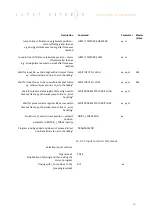
Notes for Error 50 


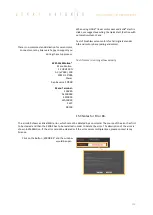
Error 50 means that deviation from position target 

value to actual position value is higher than 

„DEVIATION POS

 ACT

 (


WebMotion®, setup, state 

controller

). 

There are different possible causes which lead to this 

error. Please check the following:  


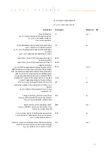
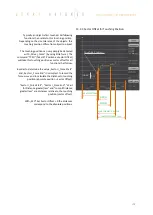
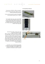
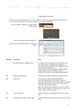
Test POSITION Encoder counter 


Status Display XENAX® WebMotion® 


When the carriage slider of a linear motor axis or the 

rotary linear motor is being moved by hand, the 

position encoder counter has to adjust accordingly. If 

not check cable, signal encoder (check A/A* and 

B/B*). 


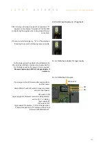
If a shaft of a rotary motor is being turned clockwise 
(when looking at front shaft), the POSITION encoder 
counter has to count positive. When turned counter 

clockwise, the POSITION encoder counter has to 

count negative. Compare to chapter Definition of 

Rotating Direction for Servo Motors. 


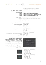
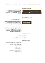
Check parameters in setup 


I STOP 

 sufficient? 

I RUN 

 sufficient? 

DEVIATION POS  

 2000 (Default) 

DEVIATION TARGET POS  

 50 (Default) 


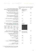
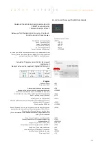
Check power supply unit 


Is there enough voltage and enough power supply? 


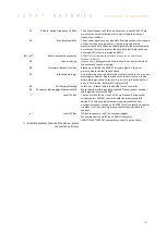
For LINAX® rotating field adjustment 

Lxc F04 at least 5,2A 
Lxc F08 at least 6,1A 

Lx F10 at least 5,5A 
Lx F40 at least 6.0A 

Lx F60 at least. 8.0A 


For ELAX® rotating field adjustment 

Ex F20 at least 5,5A 


Содержание XENAX Xvi 75V8S

Страница 1: ...ver Web browser The integrated webserver allows a setup and parameterization over web browser After an automatic self check the connected LINAX linear motor axis the ELAX electric slide or the ROTAX r...

Страница 2: ...DC EC servo motors for example from FAULHABER or MAXON can also be operated by the XENAX Xvi 75V8S The logic supply 24V DC and the intermediate circuit voltage 24V 75V DC are separately connectable Th...

Страница 3: ...tions 16 4 5 1 STO Safe Torque Off 16 4 5 2 SS1 Safe Stop 1 16 4 5 3 SS2 Safe Stop 2 17 4 5 4 SLS Safely Limited Speed 17 4 6 Functional Safety Parameterization in WebMotion 18 4 6 1 Display Active Sa...

Страница 4: ...10 5 Move Axis by Command Line 40 10 6 ASCII Command Set for XENAX 40 10 6 1 Power Reset 40 10 6 2 Basic Settings 41 10 6 3 Motor Settings 41 10 6 4 Controller Settings 41 10 6 5 Motion Settings 42 1...

Страница 5: ...18 3 Reference ROTAX und Third Party Motors 80 10 18 4 Reference to Mechanical Stop 81 10 18 5 Correction Table for LINAX ELAX 82 10 19 Basic Settings 85 10 20 Version 86 10 21 Update Firmware 87 10...

Страница 6: ...2 Force Process with ASCII Commands 106 14 Operating Status on 7 Segment Display 107 15 Error Handling 108 15 1 Error Codes 108 15 2 Notes for Error 50 112 15 3 Notes for Error 89 113 15 4 Notes for...

Страница 7: ...nput digital 12 x 24V Pull down Output digital 8 x 24V 100mA Source or 400mA Sink Input function 8 inputs to start a function or program Output function 8 outputs to indicate a condition Reference for...

Страница 8: ...402 B R CANopen DS402 EtherNet IP DS402 Allen Bradley PROFINET PROFIdrive SIMATIC SIMOTION SINUMERIK SMU Safety Functions STO Safe Torque Off SS1 Safe Stop 1 SS2 Safe Stop 2 SLS Safely Limited Speed S...

Страница 9: ...y You will find instructions for this in the manual of the bus module used on our website https www jennyscience ch en products download Xvi 75V8 Xvi 75V8S Webserver base for WebMotion Java HTML5 Opti...

Страница 10: ...pact integration of the linear motor in the slider case resulting in a force volume ratio which has hitherto never been achieved Special feature Linear motor identification and temperature monitoring...

Страница 11: ...le with brakes for vertical applications 2 3 Customary Servo Motors Faulhaber Maxon AC DC EC brushless servo motors with incremental encoder RS422 A A B B and Z Z and hall sensors as well as DC brush...

Страница 12: ...ous for the removal and mounting of a device is not necessary The distance to the base plate must be at least 40mm We recommend mounting the devices in vertical orientation with the 7 segment display...

Страница 13: ...al Note In case of any modification or attempts of modification on the hardware by third parties the T V certification is no longer guaranteed and Jenny Science declines all liability 4 2 Safety Stand...

Страница 14: ...nction SBC Safe Break Control is not available Note2 Rotative motors operating suspended loads are excluded from SS2 and SLS safety functions Commissioning The configuration assessment has to be warra...

Страница 15: ...itched safety inputs lead to turn off of the power stage and requires a restart of the XENAX servo controller Level of safety inputs 21 0V safety input inactive 2 0V safety input active Voltage levels...

Страница 16: ...through parameter ED Emergency Deceleration Indicated by superior master controller 4 5 Safety Functions 4 5 1 STO Safe Torque Off According IEC 61800 5 2 Immediate shut down of the output stage Erro...

Страница 17: ...on window is exceeded as well then triggering STO shut down of the output stage Adjustment of speed during SLS time out has to be specified by user Parameter Timeout SLS t2 Standard 300ms Safely Limit...

Страница 18: ...xplanations on WebMotion interface If the XENAX servo controller contains a Safety Motion Unit SMU but no parameters are assigned the following message appears SMU not active no parameter set The butt...

Страница 19: ...XENAX to File The safety parameters on the SMU are saved into a file open Safety parameters can also be loaded from a pc file In order to be activated on the XENAX servo controller the parameters hav...

Страница 20: ...lug Wago pitch 3 5mm POWER LOGIK 4 pole plug Wago pitch 3 5mm ENCODER HALL 15 pole plug D Sub High Density OPTIO 8 pole socket RJ45 PLC I O 26 pole plug D Sub High Density START UP MASTER SLAVE 2 x 4...

Страница 21: ...18A peak per axis Depending on mass in motion profile and power supply voltage For a fuse protection of the power supply it must be considered that a short peak current of 8A can be reached for the r...

Страница 22: ...7k to 5V pull down 2 2k differential input 26LS32 11 HALL 2 TMP Pull up 2 7k to 5V differential input 26LS32 over temperature signal motor 12 HALL 2 Middle level Pull up 2 7k to 5V Pull down 2 2k diff...

Страница 23: ...rnal Pin 1 GND 5V internal Pin 2 5V Pull up 2 7k to 5V differential input 26LS32 Pin 3 PULS Pull up 2 7k to 5V differential input 26LS32 Pin 4 DIRECTION Middle level Pull up 2 7k to 5V pull down 2 2k...

Страница 24: ...brown Input 4 24V Input Ri 31k Pin 21 white blue Input 5 24V Input Ri 31k Pin 22 brown blue Input 6 24V Input Ri 31k Pin 23 white red Input 7 24V Input Ri 31k Pin 24 brown red Input 8 program Start 2...

Страница 25: ...put SOURCE SOT 21845 SOA 255 0 TYPE SINK SOT Bit value TYPE SOA Bit value ACTIVITY Output ON Output OFF 0 0 SINK 1 HIGH open 0V 0 LOW 0V open All Output SINK SOT 0 SOA 255 0 TYPE SOURCE SINK SOT Bit v...

Страница 26: ...r Values Output SOT Bit SOT Bit value TYPE SOA Bit SOA Bit value ACTIVITY Output ON Output OFF 1 0 1 0 0 SINK 0 0 HIGH 0V open 0 1 LOW open 0V 2 2 3 0 1 SOURCE 1 0 LOW open 24V 1 1 HIGH 24V open 3 4 5...

Страница 27: ...e XENAX Servocontroller recognises if the connected motor is a Jenny Science motor LINAX Lx ELAX Ex or ROTAX Rx or a motor from another manufacturer typically a rotative servo motor and configures the...

Страница 28: ...Bit Parity kein Stop 1 Bit 7 2 RS232 Operation Optionally the USB COM socket can be used as a plain RS232 interface Note that the XENAX must be ordered with this option because hardware changes are r...

Страница 29: ...the IP address displayed on the 7 segmet display To do this switch on the logic supply and switch it off again while the dot on the 7 segment display is blinking The next time you switch it on the IP...

Страница 30: ...able 8 3 Close Port 10001 If the port 10001 is not closed correctly it can stay open In this case it is no longer possible to connect to this port with a new TCP IP connection There are 3 options for...

Страница 31: ...P CR TP CR LF XXXXXXX CR LF Retrieve e g AC SP CR CR AC CR LF XXX CR LF SP CR LF XXX CR LF Echo command not recognized or cannot be completed in the current configuration command CR LF CR LF Echo comm...

Страница 32: ...events Therefore it is not necessary to poll the status or inputs permanently Enable Events Events disabled default EVT 0 Events enabled generally EVT 1 Status modifications Reference Event Will be s...

Страница 33: ...active again Events OFF EVT 0 PLC Input Events OFF DTI 0 10 WebMotion Please also consult the TUTORIAL Video JSC Tutorial 2 Set Up Single Axis on our website and convince yourself of the easy axis set...

Страница 34: ...XENAX logic supply is interrupted or if the Ethernet cable is disconnected the TCP IP interruption will be detected by WebMotion and signaled with offline After removing the cause of the offline mode...

Страница 35: ...voltage input functions functionality of the measuring system parameter settings and current flow of the linear motor In order to test the functionality of the measuring systems the system asks you to...

Страница 36: ...increments of the measuring system Standard for LINAX ELAX linear motors is 1Increment 1 m MOTOR Automatic identification of the connected LINAX ELAX ROTAX motor axis If a third party rotary motor is...

Страница 37: ...er These parameters will overwrite the existing values and will be registered directly in the XENAX servo controller SOFT LIMIT POS Software Limit Position setting of an individual motion range in inc...

Страница 38: ...verse in units of 1 milliseconds Start with Enter TIME ms Time of the last profile drive in milliseconds Reference Reference drive REF Executes the reference drive to calculate the absolute position R...

Страница 39: ...near motor axis or a ROTAX rotary axis XENAX assumes a connection with third party motor Instead of Go Pos 0 WebMotion offers Jog und Jog functions Jog Runs the motor in negative direction until the c...

Страница 40: ...e Information about the tables Diagnosis and test functions Query of the programmed value 10 6 1 Power Reset DESCRIPTION Short CMD PARAMETER Power ON incl reset encoder counter Power PW Power ON conti...

Страница 41: ...10 1 800 Pole pair number of motor Pole pair POL 1 100 Number of encoder increments per revolution Encoder ENC 10 32 000 Direction of phase control u v w or v u w Phase Direction PHD 0 1 Detection of...

Страница 42: ...000 000 000 Way relative encoder increment Way WA 2 000 000 000 Way relative encoder Inkrement initial value after powerup Way Initial Value WAI 2 000 000 000 Speed Inc s encoder counter Speed SP 10...

Страница 43: ...REF positive motors reverse direction 5 Gantry REF negative motors reverse direction Direction REF DRHR 0 5 Responds the automatically detected Gantry Master Salve Offset Important The command DGMSO...

Страница 44: ...T 1 10 000 ms Waiting time for command RR and RW initial value after powerup Wait Repeat Initial Value WTI 1 10 000 ms Run index number Index IX 1 50 Run profile Profile PRF 1 5 Move DRIVE I_FORCE Nr...

Страница 45: ...x x1 000 inc s2 Acceleration of selected Drive I_Force ADIF xx Speed for Drive I_Force xx inc s Speed of selected Drive I_Force SDIF xx Limitation of I Force current while Drive I_Force xx x10mA I_For...

Страница 46: ...LOW active 2 individual input activity selection according to ILAS value 0 and 1 puts ILAS to 0x000 respectively 0xFFF Input LOW active ILA 0 2 individual input activity selection 0 Input HIGH active...

Страница 47: ...mit stop negative 0 Deletes the position of the detected external mechanical limit stop negative Note MLPN always needs to be chosen smaller than MLPP If MLPN is deleted MLPN 0 the value for the inter...

Страница 48: ...d FCV xx Automatic I_Force Drift Compensation Drive in positive direction I_Force Drift Compensation Positive IFDCP Automatic I_Force Drift Compensation Drive in negative direction I_Force Drift Compe...

Страница 49: ...EC Retrieving the selected sector number Number of Sector for change parameter NSEC xx Sector start distance xx Inc starting distance current position sector offset Sector I Force Start SIFS xx Sector...

Страница 50: ...alue Correction Table State CTAB 0 2 Starting position of the correction table in inc Correction Table Position Start CTPS 0 500 000 000 Distance between the entries in the correction table in inc Cor...

Страница 51: ...T 17 SS2 PRIMED BIT 18 SS2 HIT BIT 19 SLS PRIMED BIT 20 SLS SPEED HIT BIT 21 SLS POSITION HIT BIT 22 WARNING BIT 23 INFORMATION BIT 24 PHASING DONE BIT 25 I_FORCE_DRIFT_COMPENSATION_DRIVE_ACTIVE BIT 2...

Страница 52: ...seconds in Cyclic Synchronous Position Mode DS402 Used RMR for interpolation Only multiple of 100 micro seconds possible PDO Cycle Time PCT 100 10 000 Versions number of the installed bus module firmw...

Страница 53: ...ncoder plausibility test off for rotary motors only Encoder Plausibility Checking Disable ENCPD 0 1 Watchdog for Serial Ethernet interface 0 deactivated 1 60 000 Watchdog time in ms If output stage is...

Страница 54: ...gram Recording position acceleration IForce and position deviation LOGGING AUTO Recording starts as soon as the drive has started The record lasts until the drive and a possible program have ended LOG...

Страница 55: ...ouse over a time section this part can be zoomed The Reset button undoes the zoom action With the Pan key the time axis can be moved with the mouse Command Enter command e g starting position of the m...

Страница 56: ...simplify programming and reduce the communication time by serial control Execute with IXxx CR A maximum of 50 INDEXES can be predefined NEW Create new index Parameter of the Index ACCx1000 SPEED DISTA...

Страница 57: ...lears the Drive I_Force EXECUTE Drive I_Force will be executed COPY TO DIFxx Drive I_Force will be copied into a new Drive I_Force 10 11 Sector I_Force In the WebMotion program menu sector I force up...

Страница 58: ...ll defined program lines of the present program will be shown Maximum number of lines depends on program mapping PMAP default 0 PMAP 0 Prog 1 15 50 lines Prog 16 63 10 lines PMAP 1 Prog 1 5 130 lines...

Страница 59: ...NPUT NR HIGH xx MS Wait to logical Low of Input number xx within timeout frame yy otherwise jump to line zz error handling timeout can only be used locally not for remote WAIT INPUT NR LOW xx MS Set p...

Страница 60: ...ORCE will overwrite the current parameter I_Force in DRIVE I_FORCE until DRIVE I_FORCE END CHANGE LIMIT I_FORCE xx Jump to line zz if distance xx absolute position sector offset greater than xx e g dr...

Страница 61: ...stroke of the motor In this example the axis drives to start position 0 Important The command REFERENCE has to be completed once after powering on the servo controller Only after reference other moti...

Страница 62: ...physical output ON und OFF of the outputs by mouse click INPUT FUNCTIONS Assigning input functions to a physical input Choice of high or low activity of all inputs Input 9 12 binary coded In the oper...

Страница 63: ...PTURE POSITION Interrupt program while Input active INTERRUPT PROGRAM Stop Impulse edge triggered If a LINAX is connected it behaves like STOP IMPULS COUNTER STOP IMPULS Stop Impulse Counter like STOP...

Страница 64: ...ong as EMERGENCY EXIT is active no other function can be executed For the other functions the following applies If another function is already active it has to be finished before the next one is start...

Страница 65: ...back 2 SLS2 Feedbacks are status information and not SMU safety functions Only possible with optional SMU Safety Motion Unit 10 13 3 Operation with Additional Holding Brake An additional holding brake...

Страница 66: ...list contains all predefined profiles PARAMETERS Set up of the parameters in CURRENT PROFILE S CURVE Percentage S curve rounding of the profile Automatic calculation of jerk parameter for each profile...

Страница 67: ...actual position controlled by edge With each increasing edge at input 12 the current position of the motor is written in a buffer register Start is Captured Pos 1 Reaction time 4 6 s First edge positi...

Страница 68: ...a gear transmission ratio of 20 1 we need to reduce the external torque of inertia by a factor of 400 For direct drive linear motors it is important to set the parameter for the moment of inertia of...

Страница 69: ...til the status in position comes up Default Standard setting of the different parameters All parameters can be manually modified during the controller tuning and can be reset to default values with th...

Страница 70: ...illation Setting one of the two parameters at 0 disables this feature Important Note The calculation of the target trajectory can not be abruptly changed in motion After setting a new value for freque...

Страница 71: ...me applications usually with high payloads it sometimes happens that no setting can be found that meets both criteria If the motor with a set band width begins to oscillate because of a resonance in t...

Страница 72: ...h a running program or through a superior PLC Turned on During the frequency analysis the axis moves to the indicated position within the selected recording time F Analysis Starts the frequency analys...

Страница 73: ...oximate middle of the resonance frequency On frequency 0 the mean current will be displayed during the frequency analysis It corresponds to the DC portion of the motor current which is rarely 0 Diagra...

Страница 74: ...pairs 1 INC PER REVOLUTION Number of encoder increments per revolution Linear motor axis Lxc 44F04 INC PER REVOL 12 000 other LINAX products Lxc Lxe Lxu Lxs INC PER REVOL 24 000 ELAX INC PER REVOL 14...

Страница 75: ...PHASE DIRECTION Direction of phase control U V W or V W U depending on motor type Can be detected with command PHDD With DC brush type servo motors PHASE DIR 0 if motor shaft turns clockwise with dir...

Страница 76: ...0 INC PER REVOLOLUTION Number of encoder increments per revolution by AC DC EC brushless servo motors Not used for DC brush type servo motors PHASE DIRECTION Direction of phase control U V W or V W U...

Страница 77: ...um position values correspond to 231 1 2 147 483 647 inc in positive direction and 231 2 147 483 648 inc in negative direction The overflow takes place between these two values 2 147 483 647 2 147 483...

Страница 78: ...ion up Away from absolute zero point in positive direction NEGATIVE Reference direction down direction towards absolute zero point GANTRY POS Motors in same direction up in positive direction away fro...

Страница 79: ...e position stroke ELAX 1mm 10 18 2 2 Reference with External Limit If there are externally mounted limit stops MLPN 0 or MLPP 0 the reference REF will be completed to one of the externally mounted lim...

Страница 80: ...ON SHORTEST WAY shortest way only possible at ROTAX Rxvp Z MARK SPEED Speed to search the Z mark If no Z mark Reference mark exists then set this value to 0 CLEAR OUPTPUTS Set all outputs to OFF after...

Страница 81: ...ative CREEP SPEED Speed to mechanical stop Inc s CURRENT LIMIT Nominal motor current x10mA during reference Power F motor current x force constant REF WINDOW Maximal allowed variation compared to last...

Страница 82: ...n the entries of the table can be defined If for example the range 0 100 000 increments shall be corrected the starting position is 0inc and the distance for the 50 remaining table entries is 2 000 in...

Страница 83: ...the correction table will be initialized and deactivated physical position encoder position During the measurement of the physical position values the correction table has to be deactivated Encoder P...

Страница 84: ...e position 0 REF Absolute position is calculated next to the 0 point This is repeatable at the same position G0 Go to absolute position 0 Now the Linear motor axis is ready Remark The position WebMoti...

Страница 85: ...ded Prog No stepper control 12 INC PER PULSE Inc pro Pulse MODE 2 Puls Direction controlling SYNC RATIO Ratio of electronic gear CARD IDENTIFIER Master Slave CANopen Powerlink Read form start up key 2...

Страница 86: ...mware WebMotion hardware and MAC address BUS MODULE Optional bus module with version indication and protocol type Mac address issue with Profinet Powerlink and EtherNet IP If the Mac address is 0 the...

Страница 87: ...ion of firmware download reset servo controller with command RES reset in menu move axis by command line Reload the application into WebMotion and download it to servo controller WebMotion Update from...

Страница 88: ...tions from WebMotion to a file on PC Laptop Harddisk Server to start up key Saves applications in the start up key to load faster on other XENAX If with Ethernet settings is checked the Ethernet setti...

Страница 89: ...1 Master Slave Configuration Master and slave devices are absolute identical standard XENAX servo controllers The I2C bus is interconnected via short standard USB patch cables Both plugs USB A are usa...

Страница 90: ...lly transferred to the slaves 11 3 Timing Master Slave The program interpreter is triggered in 1ms intervals The transmission of a command from the master to the slave takes an additional 0 45ms The m...

Страница 91: ...which will be communicated by ASCII commands is the master The slave has to be connected to the master via A A cable The slave has to be assigned a CARD IDENTIFIER between 1 and 3 This can be done by...

Страница 92: ...Go direct Position GW Go Way IX Index PRF Start profile No xx PG Program EE Emergency Exit EE1 Emergency Exit 1 SM Stop Motion EE and EE1 must only be parameterized in a Gantry Master Can also be tri...

Страница 93: ...n object or an end position if there are no objects e g inserting parts Or driving with very little force in order to detect an object s touching position FORCE MONITORING Monitoring the force progres...

Страница 94: ...ration 13 1 2 Force Limitation The current value I_Force is proportional to the force Following graph shows corresponding relations for the different linear motor types LINAX Linear Motor Axis Force C...

Страница 95: ...force specifications are defined with the in the force sector incoming and exiting sector boundaries Force Specification Examples 1 Force curve has to pass through sector from the left bottom side to...

Страница 96: ...FORCE CONTROL can be combined and defined with the use of the according commands 13 1 4 2 Drive I_Force DRIVE I_FORCE is driving with force consisting of acceleration ACCEL speed SPEED current I_FORCE...

Страница 97: ...o xx x 10mA Value of I_FORCE will overwrite the current parameter I_Force in DRIVE I_FORCE until DRIVE I_FORCE END CHANGE LIMIT I_FORCE xx Is taking the actual position as offset value for all sectors...

Страница 98: ...rwise jump to line zz error handling WAIT INPUT Nr LOW xx yy zz MS Wait for process status register Bit xx High within timeout frame yy otherwise jump to line zz error handling WAIT PROCESS STATUS BIT...

Страница 99: ...ation Bit2 Continuous compensation at enabled power stage at applicable position see command PIFDC IFDCS 0 7 Position for I_Force Drift Compensation at enabled power stage depending on the motor type...

Страница 100: ...d Jump if distance greater less are adjusted by this offset TPSO typically touching position also refer to chapter 13 2 3 Sector Offset for Touching Position Provide offset for all sectors with restar...

Страница 101: ...adezimal decimal Definition of transitions Entry and Exit in sector xx activated transition 1 2 3 4 Entry Exit STCX hex STC dec xx Number of Drive I_Force to change parameter Selecting Drive I_Force n...

Страница 102: ...hing position as sector offset for all functions that follow In order to determine the value Sector I_Force Start and Sector I_Force End it is simplest to record the force curve and to calculate the d...

Страница 103: ...n the force curve of the ceramic plate shall be recorded After an air gap of only 200 m the ceramic plate hits the rubber buffer At this position the force increases steeper as the rubber buffer acts...

Страница 104: ...recognize touching position 1N 12 x 10mA Drive I_Force 1 Acc x1000 100 Speed 5000 IForce x10mA 6 Direction 0 In order to determine the following sector parameters we recommend the following approach 1...

Страница 105: ...error no object in place output 1 ON Short wait time in order to stabilize touching position Takes touching position as offset for the following tests Selecting sectors 1 5 Change I_FORCE forcurrent D...

Страница 106: ...om 0 until 50000 Inc one time Force Calibration test if slider is floating in balance optional Back to position control optional Sector Offset is set to 0 optional Selection of active sectors of 0 Onl...

Страница 107: ...EMERGENCY_EXIT EMERGENCY_EXIT POWER OFF BIT 13 FORCE_CALIBRATION_ACTIVE BIT 14 I_FORCE_LIMIT_REACHED BIT 15 STO PRIMED HIT BIT 16 SS1 PRIMED HIT BIT 17 SS2 PRIMED BIT 18 SS2 HIT BIT 19 SLS PRIMED BIT...

Страница 108: ...overriding PLC can be deactivated if the user set the CANopen Mode of operation to 0 CANopen Object 0x6060 21 Force license missing Calibration value are existing in motor but there is no force licen...

Страница 109: ...een the internal calculated position and the present motor position encoder is larger than the value defined as DP deviation position in Closed Loop setup Refer to chapter 15 2 Notes for Error 50 54 E...

Страница 110: ...contact the Jenny Science AG company 79 Wrong checksum of calibration data Force calibration or position of mechanical limit wrong Restart Force calibration ASCII fcxx or mechanical limit calibration...

Страница 111: ...y Science 97 Interlaced warnings A new warning occurred before the state which led to the previous warning was cleared Please make sure process is setup in a way where warnings cannot interlace e g dr...

Страница 112: ...l encoder check A A and B B If a shaft of a rotary motor is being turned clockwise when looking at front shaft the POSITION encoder counter has to count positive When turned counter clockwise the POSI...

Страница 113: ...low velocity With WebMotion Menu Motion S CURVE 20 AC x1 000 100 SPEED 10 000 Power Rep Reverse 10 000 Menu Terminal SCRV20 AC100000 SP10000 WA10000 PWC RR100 15 3 Notes for Error 89 The error 89 sho...

Страница 114: ...le cable break Restart XENAX 243 plausibility digital signal Invalid voltage difference of one or more encoder signals Check encoder cable cable possibly broken 244 plausibility analogue signal Unplug...

Страница 115: ...king can also be temporarily removed until the next power cycle using the DMBUS command CANopen direct command object 0x5000 value 0x5030 230 acceleration plausibility Acceleration too high Motion to...

Страница 116: ...uld deliver 24V DC and at least 300mA Provides the adapter 24V DC for the logic as well as the power 5A are required Measure logic supply 24VDC change adapter if necessary 15 5 2 Defective Firmware If...

Страница 117: ...consent of Jenny Science AG Jenny Science AG grants no guarantee on or will be held responsible for any incidents resulting from false information Information in this instruction manual is subject to...

Отзывы: