P/N 960-100175R_Rev. 6 {EDP #200824}
© 2016, JAPAN CASH MACHINE CO., LTD.
6 - 3
Calibration and Testing
Taiko™ Series Banknote Acceptor
Section 6
Re-Programming Connection Procedure
When re-programming a Taiko™ Unit the follow-
ing DIP Switch settings and cable connections are
required:
1. On the DIP Switch Block located on the right
side of the Taiko™ Unit, set DIP Switches No.1,
7 and 8 to
ON
.
2. Connect the PC, Harness and Power Supply Unit
cables to the Taiko™ Unit as shown in Figure 6-1
on page 6-1 of this Section.
Ensure that the Taiko™ Unit is connected to the
PC using a Taiko™ Harness “B” to ensure the
proper connection is made to the Taiko™ Unit.
3. Turn the Taiko™ Unit power
ON
.
4. Check that the Front Panel Taiko™ LED flashes
White.
5. Set DIP Switch No.1 to
OFF
.
6. Check that the Taiko™ LED is extinguished.
Serial Number Writer Application Use
When replacing a Taiko™ CPU Circuit Board, per-
form the following steps to write a new Serial
Number onto it:
1. Refer to the previous "Software Downloading
Procedure" on page 6-1 of this Section to prop-
erly perform a PC Software Download, and to
Figure 6-1 on page 6-1/Figure 6-3 on page 6-2 to
identify the tools, harness connections and DIP
Switch Settings required to transfer Software to
the Taiko™ Unit.
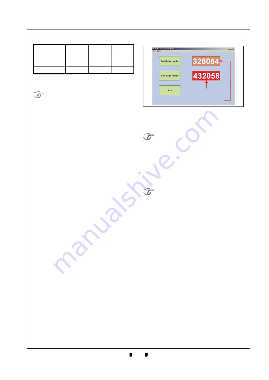
2. Double
Mouse-Click
on
SerialNo.exe
in the
Folder created in Step One (1) of "PC Program
Installation" on page 6-1, and then the following
window will appear.
3. Mouse-Click on the
Read Serial Number
Screen
Button (Figure 6-4
a
) and the current Unit’s
Serial Number will be displayed in the Text Box
next to the Button.
4. Enter a new 6-digit Serial Number in the input
Text Box next to the
Write Serial Number
Screen
Button (Figure 6-4
b
). Example: If the Unit’s
Serial Number is 03050438058, enter the last 6
digits of the Serial Number into the Text Box
(e.g., 438058).
5. Mouse-click on the Write Serial Number Screen
Button (Figure 6-4
c
) to begin writing a new
Serial Number into the Taiko™ Memory.
6. When Serial Number writing is complete, the
Taiko™ LED will flash a
Blue
Color.
7. Mouse-click
on
the
Exit
Screen Button (Figure 6-
d
) to close the Screen.
Cloning Units
Use the Clone Harness, to copy Software from a
Master Taiko™ Unit to any Slave Taiko™ Unit.
Perform this procedure as often as necessary to
copy Software to all available Taiko™ Units.
Required Items
When cloning Taiko™ Units, the items listed
below are required;
•
Taiko Unit (PUB-7/11) - Master
•
Taiko Unit (PUB-7/11) - Slave
•
JCM Power Supply
•
Taiko Harness A
•
Clone Harness
•
ID-003/MDB-Pulse/ccTalk Software
•
VM-450 Unit (for ID-001)
•
VM-450 Harness (for ID-001)
Table 6-1
Test Bench Interface Protocols
Interface
Protocol
Operating
Label
Interface
Connector
Optional
Connector
ID-003-MDB/
Pulse/ccTalk
*
*. Use JCM Power Supply Unit or equivalent. Or use Taiko™ Harness
“A” (EDP# 127527or JCME G00183 for ID-003 & G00182 for ID-0E3).
X3
Black
Yes
ID-001
†
†. Use JCM Power Supply Unit or equivalent VM-450 Harness.
01
White
No
NOTE: When a Taiko™ Unit is installed into
a Host Machine, the Power Supply Unit,
Taiko™ Harness “A” and the VM-450
Connection Harness are not required.
Figure 6-4
JCM Serial Number Writer Screen
Figure 6-4
JCM Serial Number Writer Screen
New Serial Number
Current Serial Number
a
c
b
d
NOTE: When the CPU Circuit Board is new,
nothing will be displayed in the Text Box.
NOTE: When writing a Serial Number into
Taiko™ Memory using
SerialNo.exe
, the
new Serial Number will be used as the new
Encryption Code Number.


