
B. Replacing the Power PCB Assembly
1. Ensure that all power to the power pack and the
controller is disconnected/turned off at the circuit
breaker.
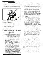
2. Detach the outer dress cover from the power pack
by pressing on each of the sides and lifting up
(see Figure 2).
3. Remove the screws attaching the cover to the back
plate and prop the cover up to expose the terminals.
Unplug the ribbon cable from the Power PCB
(see Figure 3).
4. Remove the power pack cover from the back plate.
5. Disconnect all the wires from the Power PCB.
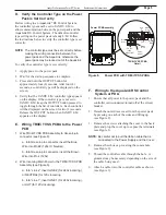
6. Keeping the wires threaded through the Power PCB
Bracket, detach the bracket from the back plate by
removing the two (2) screws and three (3) washers
(see Figure 5).
IMPORTANT
Do not discard the Power PCB Bracket
as it will be installed on the new Power
PCB Assembly.
8. Connect the wires to the Power PCB (see Section 4:
Power Pack Wiring Instructions).
9. Plug the ribbon cable into the Power PCB.
10. Reattach the cover to the back plate using the four
(4) mounting screws.
11. Reattach the outer dress cover.
12. Reconnect the power.
C. Replacing the Output Cable Assembly
1. Ensure that all power to the power pack and the
controller is disconnected/turned off at the circuit
breaker.
2. Remove the terminal cap from the cell and
disconnect the cell leads.
3. Detach the outer dress cover from the power pack
by pressing on each of the sides and lifting up
(see Figure 2).
4. Remove the screws attaching the cover to the back
plate and prop the cover up to expose the terminals
(see Figure 3).
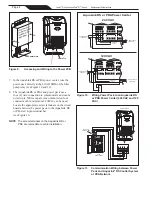
5. Disconnect the Output Cable from the Power PCB
(see Figure 6).
7.
Attach the Power PCB Bracket to the new Power
PCB Assembly. Attach the left side of the bracket
(next to fan) using one (1) screw and two (2)
washers. Attach the right side of the bracket using
one (1) screw and one (1) washer.
The extra washer on the left side will prevent the
screw from hiting the fan guard on the other side.
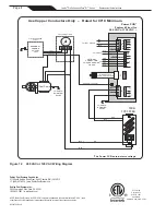
Figure 5.
Removing the Power PCB Bracket
Output Cable
(to Cell)
Power Cord
Wire to
AquaLink
®
RS System
(Optional)
Power PCB Assembly
Power PCB Bracket
Figure 6.
Output Cable Assembly Detached
Output Cable
(to Cell)
6. Remove the grommet and the cable from the Power
PCB Bracket.
7. Thread the new Output Cable assembly through the
Power PCB Bracket and secure it in place using the
grommet.
Page 3
Jandy
®
Pro Series AquaPure
®
Ei™ Series
|
Replacement Kit Instructions