


3. Installing Power Pack R-Kits
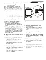
3. Remove the screws attaching the cover to the back
plate and prop the cover up to expose the terminals.
Unplug the ribbon cable from the Power PCB
(see Figure 3).
Disconnect power to the system at the main circuit
breaker before performing this procedure to avoid
risk of electric shock which can result in property
damage, severe injury or death.
WARNING
A. Replacing the Power Pack Cover
Assembly, and the Control PCB
Assembly
Disassemble to the component that needs replacement.
1. Ensure that all power to the power pack and the
controller is disconnected/turned off at the circuit
breaker.
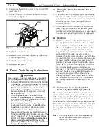
2. Detach the outer dress cover from the power pack
by pressing on each of the sides and lifting up
(see Figure 2).
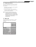
Figure 1.
Power Pack R-Kits
Outp
ut
Flow
On/O
ff
Salt
Power Pack Cover Assembly
(R0512400)
Power PCB
Assembly
(R512100)
Control PCB Assembly
(R512300)
Output Cable Assembly
(R512500)
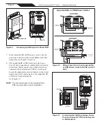
4. Remove the power pack cover from the back plate.
Turn the cover over and remove the four (4) screws
attaching the Control PCB to the cover.
5. Attach the new Control PCB to the cover using the
four PCB mounting screws provided in the kit
(see Figure 4).
Figure 2.
Power Pack Installed
Figure 3.
Unplug Ribbon Cable
Figure 4.
Control PCB Installed
Power PCB
Unplug the
Ribbon
Cable
Outer Dress Cover
To remove the outer
dress cover, press on the
sides and lift up.
6. Plug the ribbon cable into the Power PCB.
7. Reattach the cover to the back plate using the four
(4) mounting screws.
8. Reattach the outer dress cover.
9. Reconnect the power.
Page 2
Jandy
®
Pro Series AquaPure
®
Ei™ Series
|
Replacement Kit Instructions


