background image

ETL Listed

Conforms To 

UL STD 1081

Certified to 

CAN/CSA C22.2 NO. 218.1

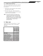
Use Copper Conductors Only  –   Rated for 90°C Minimum

RIBBON CABLE

FROM CONTROL PCB

Power PCB*

Factory Wired for

240 VAC or 120 VAC ~

*The Power PCB auto-detects voltage

Pool Pump

TO EARTH

BONDING

POINT

POOL PUMP TIMER

3

12

6

9

240 VAC or 

120 VAC

CIRCUIT BREAKER

PANEL

50/60 Hz

3 wire

Line 4 

NEUTRAL

Pump

Line 2 

120V

0V

B
A

0V

POS

BLUE

RED

RED

BLK

BLK

TO EI™ CELL

GROUND

LINE 1
LINE 2

RED

BLK

BLUE

TO FAN

OPTIONAL 

CONNECTION

TO AQUALINK® RS 

OR PDA

BLK

YEL

RED

GRN

RED

BLK

BLK

NOT USED

LOAD 2

LOAD 1

GROUND (CHASSIS)

WHT

TO EARTH

BONDING

POINT

NOT USED

NOT USED

NOT USED

TRI/Ei

TVSS PCBA

BLUE

BRN

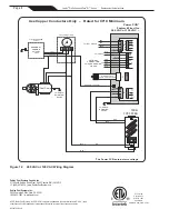
Figure 12.  240 VAC or 120 VAC Wiring Diagram

Zodiac Pool Systems, Inc.


2620 Commerce Way, Vista, CA 92081 

1.800.822.7933  |  www.Jandy.com

©2017 Zodiac Pool Systems, Inc. ZODIAC® is a registered trademark of Zodiac International, S.A.S.U., used 

under license. All other trademarks referenced herein are the property of their respective owners.
H0342700 Rev A

Page 8


Jandy

®

 Pro Series AquaPure

®

 Ei™ Series     

|

   Replacement Kit Instructions

Zodiac Pool Systems Canada, Inc. 

2115 South Service Road West, Unit 3 Oakville (ON)  L6L 5W2 

+ 1 (888) 647-4004  |  www.ZodiacPoolSystems.ca

Содержание AquaPure Ei Series

Страница 1: ...tion To order or purchase parts for the Jandy AquaPure Ei chlorine generating device contact your nearest Jandy dealer or distributor If they cannot supply you with what you need call Zodiac Pool Syst...

Страница 2: ...s and lifting up see Figure 2 Figure 1 Power Pack R Kits Outpu t Flow On O ff Salt Power Pack Cover Assembly R0512400 Power PCB Assembly R512100 Control PCB Assembly R512300 Output Cable Assembly R512...

Страница 3: ...able Assembly 1 Ensure that all power to the power pack and the controller is disconnected turned off at the circuit breaker 2 Remove the terminal cap from the cell and disconnect the cell leads 3 Det...

Страница 4: ...safety and safety of equipment B Bonding 1 The National Electrical Code NEC requires pool equipment to be bonded to each other Check your local codes to determine if the NEC and or other local install...

Страница 5: ...TVSS PCB Assembly to Green 4 pin connector see Figure 8 a Into Green 4 pin connector insert the Blue Wire into Pin 2 120v Or Neutral b Into Green 4 pin connector insert the Brown Wire into Pin 4 120v...

Страница 6: ...and AquaLink RS Control System or PDA Network Cable Tie Comm Hole Figure 9 Accessing and Wiring to the Power PCB 7 In the AquaLinkRS or PDA power center wire the power pack directly to the LOAD SIDE o...

Страница 7: ...power off to both devices and repeat steps 1 and 2 If the power pack still does not connect to the controller re check the wiring connections see Figure 10 and the controller setting on the power pac...

Страница 8: ...K RS OR PDA BLK YEL RED GRN RED BLK BLK NOT USED LOAD 2 LOAD 1 GROUND CHASSIS WHT TO EARTH BONDING POINT NOT USED NOT USED NOT USED TRI Ei TVSS PCBA BLUE BRN Figure 12 240 VAC or 120 VAC Wiring Diagra...

Отзывы: