


D. Verify the Controller Type on the Power
Pack is Set Correctly
Before wiring to an AquaLink
®
RS Control System,
the controller type must be set to JANDY L/M to
allow communication between the power pack and the
AquaLink RS Control System. The default controller
type setting on the power pack is Jandy L/M. Follow
the instructions below to verify the controller type is set
correctly.
NOTE
The controller type must be set correctly before
making the wiring connection between the
power pack and the AquaLink, otherwise the
power pack may be locked out of the AquaLink.
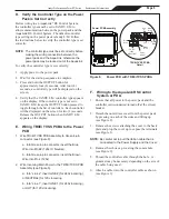
To verify the controller type is set correctly:
1. Apply power to the power pack.
2. Wait for the start-up sequence to complete.
3. Press and hold the OUTPUT button for
approximately four (4) seconds. After four (4)
seconds, a controller type will be displayed on the
screen.
4. Verify that the JANDY L/M controller type appears
on the display. If the contoller type is not set to
JANDY L/M, keep the OUTPUT button pressed to
toggle through the list of contollers. Each controller
will be displayed on the screen for two (2) seconds.
Release the OUTPUT button when JANDY L/M
appears on the display.
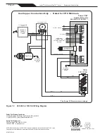
E. Wiring TRI/Ei TVSS PCBA to the Power
PCB
1. Wire TRI/Ei TVSS PCB Assembly to Green 4-pin
connector (see Figure 8).
a. Into Green 4-pin connector, insert the Blue
Wire into Pin #2 (120v Or Neutral).
b. Into Green 4-pin connector, insert the Brown
Wire into Pin 4 (120v).
2. Wire incoming Main Power to the TRI/Ei TVSS PCB
Assembly (see Figure 8).
a. Into “Line 2”, insert LINE 2 (for 240v incoming),
or NEUTRAL (for 120v incoming.
b. Into “Line 1”, insert LINE 1 (for 240v incoming),
or HOT (for 120v incoming).
F. Wiring to the AquaLink RS Control
System or PDA
1. Ensure that all power to the power pack and the
controller is disconnected/turned off at the circuit
breaker.
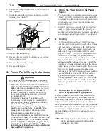
2. Detach the outer dress cover from the power pack
by pressing on each of the sides and lifting up
(see Figure 2).
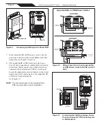
3. Remove the screws attaching the cover to the back
plate and prop the cover up to expose the terminals
(see Figure 3).
NOTE:
Be careful not to pull the ribbon cable that is
connected to the Power Supply and the Cover.
4. Remove the white cap covering the comm hole
(see Figure 9).
5. Thread the controller cable through the hole. A
grommet may be necessary depending on the size of
the cable being used.
6. Attach a cable tie to the controller cable as shown
(see Figure 9).
TRI/Ei TVSS PCBA
Detail
Pin #4
(120V)
Pin #2
(120V
or Neutral)
Blue
Wire
Brown
Wire
Power PCB Assembly
White
Wire
Black
Wire
Line
2
Line 1
Figure 8.
Power PCB with TRI/Ei TVSS PCBA
Page 5
Jandy
®
Pro Series AquaPure
®
Ei™ Series
|
Replacement Kit Instructions


