


G. Testing the Connection
Once the power pack has been wired to the AquaLink
RS Control System or PDA, follow these steps to test
the connection:
1. Apply power to the power pack and the AquaLink
RS Control System or PDA.
2. Wait about 20 seconds. If the connection was
successful, a
Ŧ
symbol will appear in the top right
corner of the power pack display.
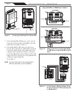
NOTE
If the power pack does not connect to the
controller, turn the power off to both devices
and repeat steps 1 and 2. If the power pack
still does not connect to the controller, re-check
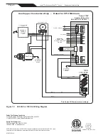
the wiring connections (see Figure 10) and the
controller setting on the power pack
(see Section 4.D).
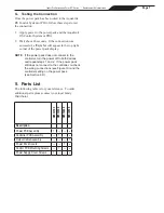
5. Parts List
The following table is for your reference. To order
additional parts, please contact your local Jandy
Distributor.
R0512100
R0512300
R0512400
R0512500
Description
Power PCB Assembly
1
--
--
--
Controller PCB Assembly
--
1
--
--
Output Cable Assembly
--
--
--
1
Power Pack Covers
--
--
1
--
Control PCB Mounting Screws
--
1
--
--
Power Supply Cover Screws
1
--
--
--
Page 7
Jandy
®
Pro Series AquaPure
®
Ei™ Series
|
Replacement Kit Instructions


