


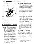

8. Connect the Output Cable wires to the Power PCB
(see Figure 12).
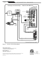
9. Securely connect the cell leads to the like colored
terminals (see Figure 7).
4. Power Pack Wiring Instructions
WARNING
When using electrical products, basic precautions
should always be followed, including the following:
• DANGER: RISK OF ELECTRIC SHOCK WHICH
CAN RESULT IN SERIOUS INJURY OR DEATH.
Before attempting installation or service, ensure
that all power to the device is disconnected/
turned off at the circuit breaker. Connect only
to a circuit protected by a ground-fault circuit-
interrupter (GFCI).
• Grounding is required. The unit should be
installed by a qualified service representative
and should be properly grounded and bonded
(See Section 4.B, Bonding).
• To avoid property damage, serious injury or
death, never use the chassis backplate of the
power pack to ground any other equipment.
• Install to permit access for servicing.
• Please read all cautions and safety instructions
in the Important Safety Instructions section of the
Jandy
®
AquaPure
®
Ei
TM
Series owner’s manual
(H0331400).
Before attempting any electrical
wiring, be sure to read and follow safety
instructions. Wiring should only be attempted
by a qualified professional.
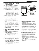
A. Wiring the Power Pack to the Power
Source
1. Wire power pack to pool pump power source using
3.3 mm
2
(12 AWG) insulated wire and conduit. The
power pack should be connected to the pump motor
switch or automatic timer (pool pump timer) as
shown in Figure 12.
2. Attach the third wire (ground) from the electrical
panel to the ground point inside the power pack.
Bonding per Section 4.B must also be accomplished
to ensure personal safety and safety of equipment.
B. Bonding
1.
The National Electrical Code
®
(NEC
®
) requires
pool equipment to be bonded to each other. Check
your local codes to determine if the NEC and/or
other local installation codes are enforced by the
Authority Having Jurisdiction (AHJ). A solid,
copper 8.37 mm
2
(8 AWG) wire is recommended,
per the NEC, for bonding the power pack to a
permanent bonding connection that is acceptable to
the local AHJ. Refer to your locally enforced codes
for the acceptable bonding wire gauge. Attach the
bonding point located on the bottom of the chassis
backplate to a common bonding point. Do not use
the power pack as the common bonding point.
Each piece of non-related pool equipment requiring
a ground should also be bonded to the common,
approved bonding point. There should be one
bonding connection to the power pack. In Canada,
the Canadian Electrical Code (CEC) dictates that
the bonding conductor be, minimum 13.3 mm
2
(6
AWG).
C. Connection to an AquaLink
®
RS
Control System or PDA (Optional)
The Jandy AquaLink RS or PDA is a multi-function
pool controller which can fully control the function
of the Jandy AquaPure Ei chlorine generating device.
Adjustment of the chlorine production rate can be
controlled from the main menu of the Jandy AquaLink
RS or PDA. The AquaLink RS or PDA offers individual
pool and spa settings for output percentage. Refer to
the AquaLink RS or PDA Owner’s Manual for more
information.
NOTE
The Jandy AquaPure Ei chlorine generating
device will communicate with all AquaLink
models Rev. K or later.
10. Reattach the terminal cap.
11. Reattach the cover to the back plate using the four
(4) mounting screws.
12. Reattach the outer dress cover.
13. Reconnect the power.
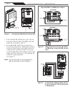
Figure 7.
Connecting Cell Leads
Red
Red
Blue
Black
Page 4
Jandy
®
Pro Series AquaPure
®
Ei™ Series
|
Replacement Kit Instructions


