JBE-P2L1 Panel Manual V1.2 EN
Page 10
Release Date: January 5, 2021
Rev 01
1.
With the batteries removed, hang the panel from the screw on the wall by passing it through the
central keyhole in the back of the panel.
2.
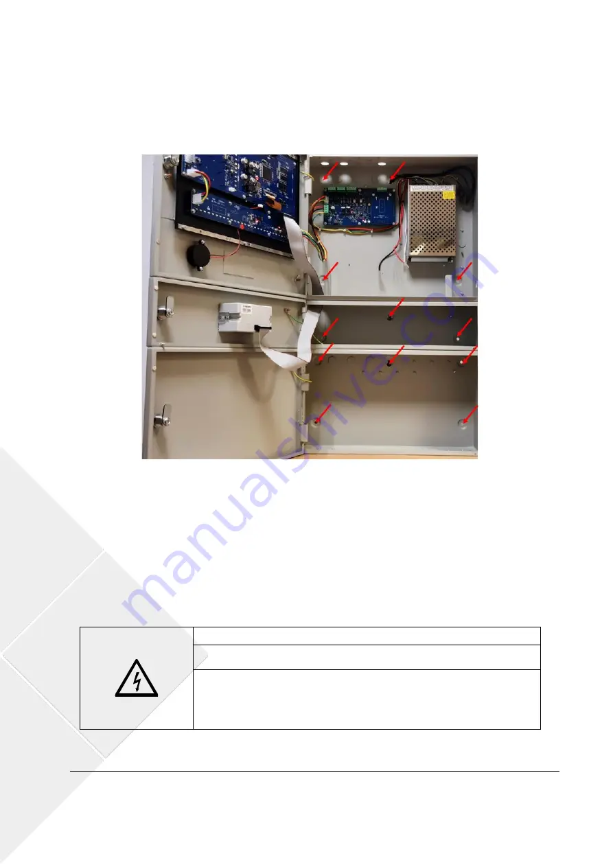
From this position, level the panel and mark the mounting hole locations:
a.
Three (3) additional holes in the panel cabinet’s backplane
b.
Three (3) holes for the printer box, if it has been installed.
c.
Five (5) holes for the battery box, if it has been installed.
Figure 3: Mounting Hole Locations
3.
Remove the panel from the wall to drill and install in it the appropriate anchors.
4.
Select the knockouts to run (separately) the mains power, detection loops and 24 V field wiring.
Remove them carefully and install a M20 wire gland in the openings.
5.
Hang again the panel from the screw on the wall. Install the load-bearing screws.
4.2.6 Electric wire connections
The door of the fire panel protects ordinary users from electric risks. The door of the fire panel must be kept
closed, locked and with the key removed. Access to the fire panel’s interior shall be restricted to instructed
users.
Voltage
– Electrical shock
Installation works must only be conducted by skilled and instructed
personnel.
When manipulating the panel interior and wires, be aware of the risk
electric shock and electric voltage.
Ensure proper lock out / tag out procedures are followed before
manipulating the panel or its wiring.


