Jabiru Aircraft
Pty Ptd
Aircraft Service Manual
Jabiru J230-C
REVISION
0
Dated : Feb 2006
Issued By: RAS
Page: 97 of 171
L:\files\Technical_manuals\J230_J430\J230.J430_Work_files\J230-C_Tech_Rev_1.doc
Print Date: 14/01/2009 4:41:00 PM
9.6
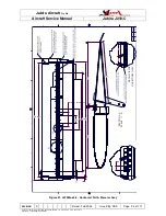
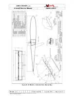
ELEVATOR TRIM CONTROL SYSTEM
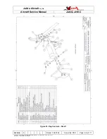
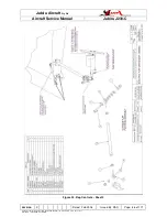
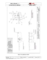
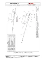
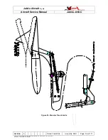
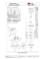
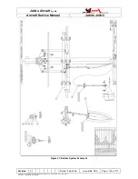
See Figure 35.
The elevator trim control system comprises a Trim Cable connected to a lubron block, so
that the cable is able to move the block fore and aft approximately 35mm. An aluminium
rod is free to slide through this lubron block and is centred by 2 compression springs. The
output end of the rod is connected to the Elevator Horn.
9.6.1
OPERATIONAL CHECK
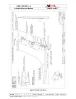
Movement of the Trim Lever FORE and AFT should result in movement of the Main
Control FORE and AFT and movement of the Elevator UP and DOWN.
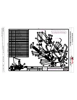
See Figure 34.
WARNING
It is important to carry out this operational check whenever the trim cable has been
disconnected to ensure it has been correctly installed.
9.6.2
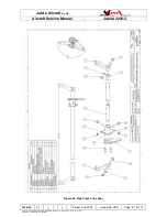
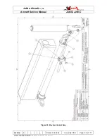
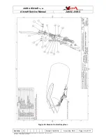
TRIM HANDLE ASSEMBLY
See Figure 34.
9.6.3
CONTROL CABLE AND ATTACHMENTS
The control cable is of the enclosed push-pull type with the cable bolted directly to the
Trim Horn Extension at the rear end and to the trim control lever at the lever end. To
operate, outer covers of the cable must be clamped firmly at both ends.
9.6.4
REMOVAL AND INSTALLATION
The Trim Control Cable is a Primary Control and may not be repaired or removed without
reference to JABIRU AIRCRAFT Pty Ltd or our approved local agent.
9.6.5
INSPECTION AND REPAIR
Inspect Trim system generally for security and any signs of wear. Pay particular attention
to the bearing blocks, friction plates, bearing, springs, cable and attachments.

