Jabiru Aircraft
Pty Ptd
Aircraft Service Manual
Jabiru J230-C
REVISION
0
Dated : Feb 2006
Issued By: RAS
Page: 135 of 171
L:\files\Technical_manuals\J230_J430\J230.J430_Work_files\J230-C_Tech_Rev_1.doc
Print Date: 14/01/2009 4:41:00 PM
13.3.1
PITOT – STATIC SYSTEM MAINTENANCE
Proper maintenance of pitot and static system is essential for proper operation of the
altimeter, airspeed indicator and vertical speed indicator (if fitted). Leaks, moisture and
obstructions in the pitot system will result in false airspeed indications, while static system
malfunctions will affect readings of all three instruments. Cleanliness and security are the
principal rules for system maintenance. The pitot tube and static ports MUST be kept
clean and unobstructed.
13.3.1.1
PITOT-STATIC WATER TRAPS
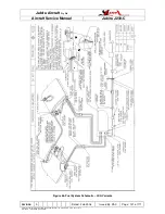
Figure 55 shows the general layout of the pitot-static system. The water trap for the static
system is located inside the ventral fin (the faring under the tail which covers the trim
mechanism). The water trap for the pitot system is located inside the fairing at the lower
end of the wing strut. Both traps should be inspected and, if necessary, drained during
scheduled maintenance. In addition, if the aircraft is parked, flown or otherwise exposed to
rain or moisture, the water traps should be checked and, if necessary, drained.
13.3.2
STATIC PRESSURE SYSTEM INSPECTION & LEAKAGE TEST
The following procedure outlines inspection and testing of the static pressure system,
assuming that the altimeter has been tested and inspected in accordance with the current
Regulations.
1.
Ensure the static system is free from entrapped moisture and restrictions. Refer to
2.
Ensure no alternations of airframe surface have been made which would effect the
relationship between air pressure in the static pressure system and truce ambient
static air pressure for any flight configuration.
3.
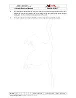
Attach a source of suction to static pressure source opening. Figure 58 shows one
method of obtaining suction.
4.
Slowly apply suction until the altimeter indicates a 1000-foot increase in altitude.
CAUTION
When applying or releasing suction, do not exceed the range of either vertical
speed indicator or airspeed indicator.
5.
Cut off suction source to maintain a “closed” system for one minute. Leakage shall
not exceed 100 feet altitude loss as indicated on the altimeter.
6.
If leakage rate is within tolerance, slowly release suction source.
NOTE:
If leakage rate exceeds maximum allowable, first tighten all connections, then repeat
leakage test. If leakage rate still exceeds maximum allowable use the following
procedure:
1.
Disconnect static pressure lines from airspeed indicator and vertical speed
indicator.

