Jabiru Aircraft
Pty Ptd
Aircraft Service Manual
Jabiru J230-C
REVISION
0
Dated : Feb 2006
Issued By: RAS
Page: 52 of 171
L:\files\Technical_manuals\J230_J430\J230.J430_Work_files\J230-C_Tech_Rev_1.doc
Print Date: 14/01/2009 4:41:00 PM
6
SECTION 6 – LANDING GEAR and BRAKES
6.1
LANDING GEAR
Main gear comprises two separate composite beams which are bolted to the fuselage at
the top and centre and to the wheel stub at the bottom.
The nose gear is a welded steel, trailing arm assembly with a rubber spring system. The
nose wheel is steerable with the rudder pedals.
Nose Wheel and Main Wheel Speed Fairings (wheel spats) are optional equipment.
6.2
TROUBLE SHOOTING – MAIN UNDERCARRIAGE
Table 5. Trouble Shooting – Main Undercarriage
Trouble
Probable Cause
Remedy
Incorrect tyre inflation
Inflate to pressure shown at
above
Landing gear attaching parts
not tight
Tighten loose parts. Replace
defective parts.
Aircraft leans to one
side
Bent axle stubs
Install new part(s)
Incorrect tyre inflation
Inflate to pressure shown in
above
Main wheels out of alignment
Align as specified above
Bent axle stubs
Install new part (s)
Tyres wear excessively
Dragging Brakes
Refer to Para. 6.8
6.3
MAIN GEAR
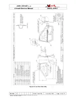
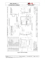
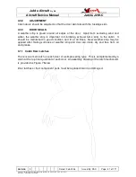
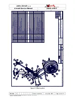
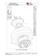
Figures 12, 15 an 14 illustrate the main landing gear. The illustrations should be used in
conjunction with the following procedures during removal and installation of component
parts.
WARNING: Check looseness of main U/C beams by lifting each wing and trying to
move beam back and forth. If movement, tighten clamp bolts (2) evenly to take
beam movement out. Do not over tighten or exceed 3 threads clear on the nuts
(use extra washers). Over tightening can cause bolt fracture and failure to tighten
both can also cause bolt failure.
(See Torque Value Figure 1-2).
The wheels comprise two wheel halves which are assembled as shown in Figure 15.
During assembly of the main wheels the through-bolts/nuts should be tightened to the
value specified in Table 2.
The assembly of the wheels to the undercarriage leg is shown in Figure 14.

