IXSEA TT801 Скачать руководство пользователя страница 3

Remote Control System TT801 – User Guide 

MU-TT801-AN rev.6 September 2009 


i

Copyright 

© 2009, IXSEA, France. All rights reserved. No part of this guide may be 

reproduced or transmitted, in any form or by any means, whether electronic, printed 

manual or otherwise, including but not limited to photocopying, recording or 

information storage and retrieval systems, for any purpose without prior written 

permission of IXSEA. 

Disclaimer 

IXSEA specifically disclaims all warranties, either express or implied, included but 

not limited to implied warranties of merchantability and fitness for a particular 

purpose with respect to this product and documentation.  IXSEA reserves the right 

to revise or make changes or improvements to this product or documentation at any 

time without notifying any persons of such revision or improvements. 

In no event shall IXSEA be liable for any consequential or incidental damages, 

including but not limited to loss of business profits or any commercial damages, 

arising from the use of this product. 

Trademarks 

Microsoft, MS-DOS and Windows are registered trademarks of Microsoft 

Corporation. Intel and Pentium are registered trademarks and Celeron is a 

trademark of Intel Corporation. 

Содержание TT801

Страница 1: ...TT801 Remote Control System User Guide...

Страница 2: ......

Страница 3: ...d but not limited to implied warranties of merchantability and fitness for a particular purpose with respect to this product and documentation IXSEA reserves the right to revise or make changes or imp...

Страница 4: ...ocument contains a general description of TT801 Details on warranty IXSEA contacts and technical support are also given Part 2 Installation This document gives the recommendations and the procedures t...

Страница 5: ...xx FR2 Reception frequency number 2 for RT6xx FSK Frequency Shift Keying FT0 Transmitted Frequency number 0 the same than CAF FT1 Frequency response to FR1 the same than CIF FT2 Frequency response to...

Страница 6: ...inciples 2 I 5 TT801 Components 10 I 5 1 Physical Description 10 I 5 2 Functional Description 13 I 6 Mechanical Environmental Characteristics 14 I 6 1 Cabinet 14 I 6 2 Dunking Transducer 14 I 6 3 Ship...

Страница 7: ...on 38 III 4 4 1 Monochromatic Transmission Interrogation Case RT6xx RT8xx RT9xx 38 III 4 4 2 FSK Transmission Cases 40 III 4 5 Case of the Pressure Measurement 43 III 4 6 Case of the Pressure Measurem...

Страница 8: ...DUNKING TRANSDUCERS 72 C 1STANDARD PET801P 30 P N 9400057 72 C 2OPTIONAL PET661S TT P N 9400051 WITH INTERCONNECT CABLE P N 9300117 73 C 3OPTIONAL AM661S ACOUSTIC MODULE P N 2809200 WITH INTERCONNECT...

Страница 9: ...ONS IT IS HIGHLY RECOMMENDED TO CONTACT THE INSURANCE COMPANY IN CASE DAMAGE IS FOUND I 3 TT801 Overview The TT801 is a low frequency 8 16 kHz transmitter system of coded acoustic signals to remote co...

Страница 10: ...te Frequency ranging from 8 5 to 16 kHz with 500 Hz steps The Release Transponder if ENABLE replies after a turn around time by sending an acoustic pulse Common Reply Frequency or Individual Reply Fre...

Страница 11: ...sponders are listed hereafter ARM it precedes the commands orders for OCEANO AR701AE AR RT ET800 AR RT ET900 series and operates like a unique address RELEASE Used with AR RT 600 series OCEANO AR RT 8...

Страница 12: ...RT800 and AR RT900 series with PINGER to activate both the release and the pinger emission upon completion of release operation TRANSP IIF TRANSP CIF Used with OCEANO RT ET800 and RT900 series to enab...

Страница 13: ...OSTIC ON FR1 OFF FR2 ON FR2 OFF FR1 PINGER FT0 FT0 FT0 FT0 and FT5 FT0 and FT7 FT0 FT0 FT0 then FT4 RT8x1 RT9x1 Yes CAF ARM RANGING RELEASE RELEASE WITH PINGER TRANSP IIF TRANSP CIF INHIBITION IIF CIF...

Страница 14: ...word command WINDOW ARM and EXECUTION sequence The factory set dual word commands are identified by the W note on the build sheet In the same way each target has its own interrogation frequencies typ...

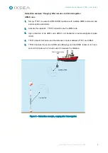
Страница 15: ...s a pulse IIF to interrogate a Recoverable transponder RT 2 Assuming the transponder channels are active ENABLE IIF CIF the RT will detect the IIF interrogation signal and transmit in turn a reply pul...

Страница 16: ...tion parameters 2 Activate the operation TT801 transmits once the ARM code 3 Upon detection of its ARM code AR8x1 unit transmits an acknowledgement pulse CAF 4 TT801 detects CAF pulse and the distance...

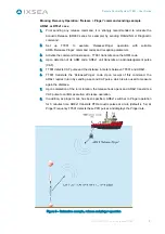
Страница 17: ...ode AR8x1 unit transmits an acknowledgement pulse CAF 5 TT801 detects CAF pulse and the distance in meters between TT801 and AR8x1 6 TT801 transmits the Release Pinger code Upon receipt of this comman...

Страница 18: ...m long Audio headphones with associated lead One user manual One factory approval form F A T Figure 4 TT801 System Components The TT801 unit is supplied as standard with the standard dunking transduce...

Страница 19: ...xample Long cable helps also in reducing the impact of vessel noise environment by getting the AM661S as far away as possible from thrusters or propellers Figure 6 Acoustic Module AM661S with integral...

Страница 20: ...lights on as soon as the TT801 is connected to AC Mains or 24V external power supply LOW red lights on when battery is in low charge state ON green light on as soon as the power switch is activated to...

Страница 21: ...ply To configure send commands To display messages and data The electronic sub assembly is made of one printed circuit board and uses low power features of CMOS technology and reliable design of IXSEA...

Страница 22: ...dard PET 801 P 30 weight 30 m cable 4 kg I 6 3 SHIPPING Dimensions 790 400 390 mm I 6 4 ENVIRONMENTAL CONDITIONS Total weight with standard PET 801 P 30 27 kg Use inside or outside Max altitude 6560 f...

Страница 23: ...0 key keyboard for data and command input Liquid Crystal Display 16 lines 20 characters Photo resistor for backlighting command Audio buzzer I 7 2 CONNECTORS The characteristics of the connectors and...

Страница 24: ...Headphones Input Front panel socket SOURIAU 851 07A 8 4 S 50 Mating plug SOURIAU 851 08 EC 8 4 P 50 Wiring A B Headphone Signal Output C D GND Electrical Ground Serial link 9 way D male socket FCT FWD...

Страница 25: ...ps to perform before running the TT801 System i e Guidelines for TT801 installation To See Know how to handle your TT801 unit II 2 Handling Know how to store your TT801 system II 3 Storage Get some in...

Страница 26: ...s be taken the disassembly process should be carried out in a clean free of dust and well ventilated area WARNING HIGH VOLTAGES OPERATION OF THE TT801 DOES NOT PRESENT ANY DANGER TO USERS IN NORMAL US...

Страница 27: ...ance and service life it is recommended that batteries which are to be stored for extended periods of time be given a supplementary charge for example 24 hours every three months At high temperature t...

Страница 28: ...ted that the Dunking Transducer or AM661S should be mounted using an acoustic isolating sleeve rubber sheeting or similar Care should be taken about dissimilar metals when the Dunking Transducer or AM...

Страница 29: ...17 to the XDC front panel receptacle The Acoustic Module AM 661 S connect the cable p n 9300102 to the XDC front panel receptacle Note For safety reasons high voltages disappear from the XDC receptacl...

Страница 30: ...ices are connected and the dunking transducer is deployed in the water the operator can switch on the TT801 cabinet At power up the configuration of the TT801 is displayed for 3 s You can check the se...

Страница 31: ...re the transmission and reception parameters III 4 Configuring the Transmission Reception Parameters Activate the transmission and reception of acoustic data III 5 Transmission and Data Reception Disp...

Страница 32: ...atever the situation in the TT801 menu you are pressing this key leads to the main screen This key is also used to leave a function of the menu and cancel the outstanding input of data SCROLL When sev...

Страница 33: ...e settings and Transmission of Commands RELEASE Summary of Transmit and Receive settings for Release operation 1 4 3 2 TRANSM IT SETTINGS Settings for transmitting DATABASE 1 LOAD 2 SAV E 3 ERASE SELE...

Страница 34: ...without saving the configuration IMMEDIATE TRANSMIT submenu or to get to the DATABASE ACCESS sub menu in order to Load a pre programmed configuration with the ID number of an instrument Save a new con...

Страница 35: ...he access to this sub menu is allowed by pressing 2 key in the menu TX RX settings Monochromatic Interrogation The user can configure a monochromatic tonal single Interrogation pulse in this case the...

Страница 36: ...M CMD sequence is required the command code mentioned on the RT6xx built sheet is followed by the W label The CODE ARM only for ARM CMD sequence and then CMD these are the hexadecimal ARM and COMMAND...

Страница 37: ...T9xx CIF Turn Around Time this is the delay between the beacon detection of interrogation and acoustic reply IRF type Mono or MSFK IRF CODE or Frequency 8 to 16 kHz RANGING it is the type of informati...

Страница 38: ...to 16 kHz RANGING it is the type of information to display Distance or Elapsed Time RT6xx series Pinger ON FT0 type MONO and Frequency 8 to 16 kHz FT4 Pinger Frequency type MONO and Frequency 8 to 16...

Страница 39: ...settings The TRANSMIT SETTINGS display opens To configure the various parameters according to the built sheet of the instrument to command perform the following procedure Step Action 1 Select the type...

Страница 40: ...onfirm Choose the frequency 8 to 16 kHz by using the SCROLL key or the numerical key for the MFSK code number 0 to 23 of the CRF Press ENTER key to confirm If the type of transmission interrogation is...

Страница 41: ...the instrument to be actuated using SCROLL key and confirm the selection by pressing ENTER key 2 Select the type of transmission TRANSMIT TYPE using SCROLL key according to individual built sheet of t...

Страница 42: ...nger AR RT8xx and AR RT9xx or Pinger ON function you also have to define the Pinger FRequency PFR FT4 for RT6xx Choose the receive type MONO or MFSK using the SCROLL key then press ENTER key to confir...

Страница 43: ...essing ENTER key The TRANSMIT Type is CMD ONLY 2 Select the type of transmission TRANSMIT TYPE according to individual built sheet of the beacon With AR6xx no other choice than CMD ONLY With RT6xx if...

Страница 44: ...eive type is MONO only No other choice Press ENTER key to confirm Choose the FT4 frequency 8 to 16 kHz by using the SCROLL key Press ENTER key to confirm 6 Select the type of the information to displa...

Страница 45: ...T801 displays the main parameters of the instruments selected To make correction of the ID use the CLEAR key A blank window opens with requirement for an ID number You must then type in an existing sa...

Страница 46: ...to the built sheet of the instrument to command perform the following procedure Step Action 1 Select key in the Device ID number IDENT To make correction you can use the CLEAR key Then press ENTER ke...

Страница 47: ...irm Choose the frequency 8 to 16 kHz by using the SCROLL key or the numerical key for the MFSK code number 0 to 23 of the CRF Press ENTER key to confirm If the type of transmission interrogation is CI...

Страница 48: ...lect the type TYPE of the instrument to be actuated using SCROLL key and confirm the selection by pressing ENTER key 3 Select the type of transmission TRANSMIT TYPE using SCROLL key according to indiv...

Страница 49: ...Pinger AR RT8xx only or Pinger ON function you also have to define the Pinger FRequency PFR FT4 for RT6xx Choose the receive type MONO or MFSK using the SCROLL key then press ENTER key to confirm Choo...

Страница 50: ...y and confirm the selection by pressing ENTER key 3 Select the type of transmission TRANSMIT TYPE according to individual built sheet of the beacon With AR6xx no other choice than CMD ONLY With RT6xx...

Страница 51: ...main parameters of the instruments selected To correct the ID use the CLEAR key A blank window opens with requirement for an ID number You must then type in an existing saved ID number and confirm by...

Страница 52: ...12 most significant bits MSB of the pressure measurement are transmitted using a pulse to pulse time modulation Time T T0 Delay that has a minimal value of the temporal encoding 2 s T1 Temporal encodi...

Страница 53: ...onfigured by saving a configuration Refer to the section III 4 4 1 to find the procedure to follow with the same specific parameters as described above Note If the automatic recurrence is selected for...

Страница 54: ...8xx IDENT 100 CMD RELEASE STD CODE ARM DCFE CMD DC55 MONO 12 0 kHZ DISTANCE ENTER TRANSMIT The display sums up the type of instrument to be remotely controlled the command and associated parameters th...

Страница 55: ...ion of the operation Upon receipt of the last CAF acknowledgement for the release execution RELEASE OK message is posted up to confirm success of the operation For Release Pinger and Pinger ON command...

Страница 56: ...t the ID use the CLEAR key A blank window opens with requirement for an ID number You must then type in an existing saved ID number and confirm by pressing the ENTER key to display the configuration o...

Страница 57: ...E ENTER VALID Step Action 1 Select the type of PFR Pinger Frequency to be detected MONO or MFSK then select the frequency using SCROLL key or the MFSK code number type in the code number and confirm b...

Страница 58: ...refreshed each time the user comes to this menu To activate the command beep This function enables or disables the BEEP audio indicator each time a character is typed in from the keyboard Note Provisi...

Страница 59: ...1 start bit 8 bits without parity MSB 0 1 stop bit The following parameters have a significant meaning Message start Fields separator Before the checksum CR LF Message end The checksum is computed by...

Страница 60: ...ure in m III 9 3 1 Transponder Command Type The answers to the commands IIF FR2 and CIF FR1 look like PMEVL XP RES RNG RT8 YP CIF 3250 CK CR LF 3250 Result giving the distance in m computed between th...

Страница 61: ...commands are Reception CAF1 PMEVL XP RES RNG RT8 YP ARM CMD 3250 CK CR LF Reception CAF2 PMEVL XP RES RNG RT8 YP ARM CMD 3251 CK CR LF Reception CAF3 PMEVL XP RES DIA RT8 YP ARM CMD 7630 CK CR LF 7630...

Страница 62: ...ilated area To See Know the TT801 Routine Maintenance IV 2 Routine Maintenance Know the TT801 Corrective Maintenance IV 3 Corrective Maintenance Locate the equipment fault IV 4 Troubleshooting IV 2 Ro...

Страница 63: ...compatible with TT801 cabinet The LOW LED indicator lights on to report a low battery The charging can be performed during TT801 operation DC voltage must be higher than 28V DC to insure proper batter...

Страница 64: ...use alcohol or petroleum solvents Transducer should not be connected to the TT801 cabinet Step Action 1 Acoustic Transducer Immediately after recovery from water rinses and washes in fresh water Check...

Страница 65: ...g plug to discharge the capacitor of the transducer Capacitance meter ISO Tech DM9023 or Data Precision model 938 or equivalent or LCR Bridge Transducer should not be connected to the TT801 circuitry...

Страница 66: ...itself as well The fuses are located on the lateral walls of the power unit see Figure 12 They are indicated by the icon below that refers to this document for further information Figure 12 Fuse loca...

Страница 67: ...battery fuse 5A 250V ref 5A HPC TDC Switch off the TT801 cabinet Unplug both cables acoustic transducer and AC Mains Step Action 1 Loosen the ten screws that fit the front panel on its case with the...

Страница 68: ...ns AC fuse 5A 250V ref 5A HPC TDC Switch off the unit Unplug both cables acoustic transducer and AC Mains Step Action 1 Loosen the ten screws that fit the front panel on its case 2 Remove the front pa...

Страница 69: ...itched OFF storage capacitors are automatically discharged Make sure you have the following items A flat blade screwdriver 6 5 X 150 mm A 7mm tube spanner 10 off M4 A4 NYLSTOP Nuts available from IXSE...

Страница 70: ...minutes 4 Disconnect the 3 cable terminals blue brown and yellow green from AC Mains filter Disconnect the white flying plug of the Battery pack from the TT801 PCB Disconnect the brown flying of the...

Страница 71: ...yellow wire from battery pack 1 and 2 7 Reconnect the orange black and yellow wires to the new batteries check polarity Insert the new packs and fit each bracket with new M4 A4 NYLSTOP nuts Tighten th...

Страница 72: ...ovement contact the IXSEA support TT801 does not receive acoustic pulses Connection problem Electronic Transducer failure Configuration problem or problem with environmental conditions 1 Check that th...

Страница 73: ...trued as covering defects malfunctions or damages caused by improper use or inadequate maintenance of the product Under no circumstances shall IXSEA be due to provide repair or replacement under this...

Страница 74: ...is available by e mail support ixsea com by phone through IXSEA 24 7 hot line 33 0 1 30 08 98 98 for EMEA 1 781 937 8803 or 1 888 660 8836 toll free for US 65 6747 7027 for Asia Contact IXSEA support...

Страница 75: ...49 511 123 59 576 IXSEA bv THE NEDERLANDS Tel 31 23 750 5110 Fax 31 23 750 5111 IXSEA Ltd UK Main Office UK Aberdeen Tel 44 0 2392 658252 Tel 44 1224 355 160 Fax 44 0 2392 658253 Fax 44 1224 826 622...

Страница 76: ...frequencies from 8 5 to 16 kHz resolution 500 Hz Pulse width 11 ms Acoustic source level 190 4dB ref 1 Pa at 1m Transducer beam pattern omni directional 3dB Transmit Receive Algorithm for Single Puls...

Страница 77: ...rrogations CODE 1 TRANSMISSION No KEYBOARD DISABLED Single code 7XX series Yes No Tempo 5 s CAF No Tempo 10 s End of tempo Yes No CAF End of tempo No No Yes Tempo 4 s CAF No End of tempo No Yes Yes No...

Страница 78: ...OURIAU 6 way male socket for external 24 VDC power supply SOURIAU 4 way female socket for Headphones input 9 way D male socket for RS232 422 serial link Provisional AC DC LED indicator for external po...

Страница 79: ...71 B FREQUENCY TO DIGIT CONVERSION TABLE Transmission Frequency Frequency Code Bit_0 or Bit_1 Channel kHz TT301 TT801 TT201 8 5 0 1 9 0 1 2 9 5 2 3 10 0 3 4 10 5 4 5 11 0 5 6 11 5 6 7 12 0 7 8 12 5 8...

Страница 80: ...Remote Control System TT801 User Guide MU TT801 AN rev 6 September 2009 72 C DUNKING TRANSDUCERS C 1 Standard PET801P 30 P N 9400057...

Страница 81: ...Remote Control System TT801 User Guide MU TT801 AN rev 6 September 2009 73 C 2 Optional PET661S TT p n 9400051 with interconnect cable p n 9300117...

Страница 82: ...le plug SOURIAU series 4 pins Male plug SUBCONN series Ref Ref 451 01 EC14 12P iXSea ref P O8EC14 12P Plug OM4 M iXSea ref P OM4 M Boot OMBA iXSea ref P OMBA Locking DLSA M iXSea ref P DLSA M FRONT VI...

Страница 83: ...Remote Control System TT801 User Guide MU TT801 AN rev 6 September 2009 75 C 3 Optional AM661S Acoustic Module p n 2809200 with interconnect cable p n 9300102...

Страница 84: ...NN series 851 08EC1412P50 iXSea ref P O8EC14 12P Plug OM8F iXSea ref P OM8F Boot OMBB iXSea ref P OMBA Locking DLSB F iXSea ref P DLSB F FRONT VIEW TT side AM side Ground ISO2 Power AM 0V DC A Brown M...

Страница 85: ...omer Visa Modification Affair TECHNICAL SPECIFICATIONS ELECTRONIC BOARD ELECTRONICAL SPECIFICATIONS Reference Rev Function S N Transmit width 10 ms Transmit level 190 dB 3 dB ref 1 P at 1m 194 2003 4...

Страница 86: ...er Visa Modification Affair TECHNICAL SPECIFICATIONS ELECTRONIC BOARD ELECTRONICAL SPECIFICATIONS Reference Rev Function S N Transmit width 10 ms Transmit level 191 dB 4dB ref 1 Pa at 1m 194 2002 6 RT...

Страница 87: ...43 FT0 RELEASE 1 2844 BIT0 BIT1 44 FT0 FT5 DIAGNOSTIC 2845 BIT0 BIT1 45 FT0 FT7 Measure delay 3s Verticality Offset 10s WINDOW ARM 2841 BIT0 BIT1 41 FT0 Wait time 15s Active time 15s ON FR1 OFF FR2 W...

Страница 88: ...file Modification Customer approval TECHNICAL SPECIFICATIONS ELECTRONIC BOARD ELECTRONIC SPECIFICATIONS Reference Rev Function S N 392 2001 3 0 AR 8x1 Board 276 Firmware PROM U6 ET8_V2 2 FPGA U38 REC_...

Страница 89: ...1 TT701 TT301 TT201 Sequence ARM RANGING 141C N A CAF Lock Out time 4s Active time 20s The following acoustic codes must be preceded by an ARM code RELEASE 1455 N A CAF CAF RELEASE WITH PINGER 1456 N...

Страница 90: ...10 ms Transmit level 191 dB 4 dB ref 1 Pa at 1 m Transmit delay Turn around time 20 ms Turnaround delay 4 s Pinger rate 5 s Pinger duration after release 3 mn CIF 09 0 kHz IRF 13 5 kHz IIF 13 5 kHz C...

Страница 91: ...m TT801 User Guide MU TT801 AN rev 6 September 2009 83 PINGER ON ARM 0347 N A CAF PINGER PINGER OFF ARM 0348 N A CAF DIAGNOSTIC ARM 0349 N A CAF1 CAF2 ACOUSTIC RESET ARM 034A N A CAF ST Default operat...

Страница 92: ...PECIFICATIONS ELECTRONIC BOARD ELECTRONIC SPECIFICATIONS Reference Rev Function S N 359 2002 1 1 AR 701 board 149 Firmware V1 12 FR2 14 0 kHz FR1 15 0 kHz FUNCTIONAL SPECIFICATIONS Function Code TT301...

Страница 93: ...68 Reception 1 Single Pulse 68 Transmission 1 Charging Battery 55 Codes Command 68 Commands codes 68 Configuration Deleting 43 Loading 37 Saving 38 Configuring FSK Parameters 33 Immediate Settings 31...

Страница 94: ...stic Reception 6 TT801 Acoustic Transmission 2 Reception Characteristics 1 DISPLAY 46 Parameters 29 30 Reinforced Transducer PET 661 S TT 10 Replacing Battery Fuse 59 internal Battery 61 62 63 Mains F...

Отзывы: