


Regency
®
Model 4724 Control Expander Installation Manual (P/N 150596-02, Rev. A)
Revised 8/98
58
…
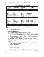
RLY[2].7
Output on 4180 Module 1, Connector P3, Pin 1
TER15
Active low output sink on Terminal 15 of the 4720 panel (50 mA)
TER16
Active low output sink on Terminal 15 of the 4720 panel (50 mA)
TER18
High output source on Terminal 18 of the 4720 panel (20 mA)-
supplies 12 VDC when turned on
X10[1]
Outputs to X-10 Modules 1-8 of House Code 1
X10[1].0
Outputs to X-10 Modules 1 of House Code 1
X10[1].1
Outputs to X-10 Modules 2 of House Code 1
…
X10[2]
Outputs to X-10 Modules 9-16 of House Code 1
X10[3]
Outputs to X-10 Modules 1-8 of House Code 2
X10[4]
Outputs to X-10 Modules 9-16 of House Code 2
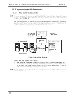
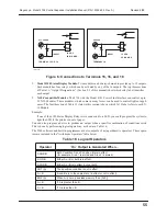
NOTE
On connectors P2 and P3 of the 4180, the designation “.0” refers to Pin 8 and the
designation “.7” refers to Pin 1.
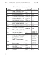
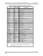
Table 20: Programmable I/O Status Labels (Read-Only)
1
Label
2
Data Type
Function
AARMED[8]
BIT
Area[n] armed
ACCAREA[8]
BIT
Window group status
ACHIME[8]
BIT
Area[n] in Chime mode
ACODE2[8]
BIT
Area[n] in Code2 mode
AENTRY[8]
BIT
Area[n] in entry delay
AEXIT[8]
BIT
Area[n] in exit delay
AINST[8]
BIT
Area[n] instant mode
ALMAREA
BITS
Areas in alarm
ALMTYP
NUMBER
Current alarm type
AREADY
BIT
Area[n] ready
ATROUBLE[8]
BIT
Area[n] zone trouble
AUDALM
BIT
Any alarm not silent
AUDAREA
BITS
Areas using audio
AUXALM
BIT
Auxiliary alarm type
AUXRLY
BITS
Auxiliary control relay status
AZONES[18]
BITS
Zones that are armed
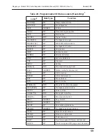
Table 19: Output Designations
Label
Function


