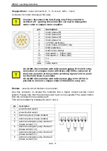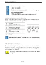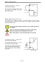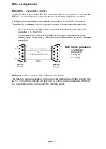
iMC-S8
– operating instruction
page - 22
4.3.1 DIP-switch settings
The controller iMC-S8 has four stepper motor power amplifiers MD28. Settings for
rated current, step resolution and current reduction takes place by the DIP-switch on
the top side of the amplifiers case.
Configuration of the controller should be done before first start-up
so that a connected motor will not be damaged because of an
incorrect power setting.
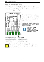
To configure the step resolution and motor current open the cover and set the jumper
on each amplifier as follows (more information /1/ Microstepping Driver MD24/MD28):
DIP Switch - MD28 in iMC-S8
1:
current setting 1
2:
current setting 2
3:
current setting 3
4:
current reduction
5:
step resolution 1
6:
step resolution 2
7:
step resolution 3
8:
step resolution 4
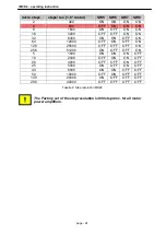
Current setting (DIP-switch 1, 2, 3)
Use the DIP switches 1, 2 and 3 to set the current of the motor. The following table
shows the motor current (RMS) setting for the different switch positions:
Peak current[A]
Rated
current[A]
SW1
SW2
SW3
MD24
MD28
MD24
MD28
1.00
2.80
0.71
2.00
ON
ON
ON
1.46
3.50
1.04
2.50
OFF
ON
ON
1.91
4.20
1.36
3.00
ON
OFF
ON
2.37
4.90
1.69
3.50
OFF
OFF
ON
2.84
5.70
2.03
4.10
ON
ON
OFF
3.31
6.40
2.36
4.53
OFF
ON
OFF
3.76
7.00
2.69
5.00
ON
OFF
OFF
4.20
7.80
3.00
5.57
OFF
OFF
OFF
The factory set of the motor current is 2.03 A (RMS) at MD24 and
3.00 A (RMS) at MD28 on all motor power amplifiers.


