£x
isel-
Ê«>VÌʵիiÌÊÊ*
*
0
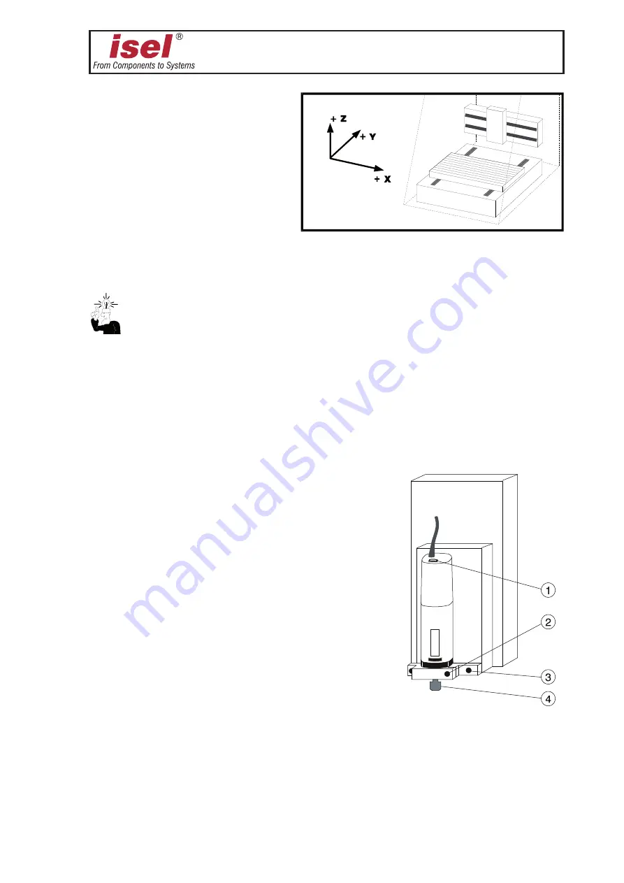
Coordinate system
The coordinate system of the
machine is determined as shown
in the figure. However, you can
select (displace) the P0 work
piece zero point freely via
software.
Ex works, the home position of
the machine (machine origin) is defaulted to the back (Y), to the left (X), and to the top (Z).
Labels on the machine mark the axes.
The order of the axial directions is freely selectable. Please, read the manual of the I5DRV
driver for this purpose.
Tooling machine
(only in the case of type 3)
In the collet
➃
, the standard tooling machine can take tools with a maximum shaft diameter
of 6.35 mm (standatd 3 mm, other diameters see Accessory). Use two SW 22 open end
wrenches for changing the collet.
The current for the tooling machine is only enabled by
the software. You can manually adjust the rotation
speed of the machine using the
➀
wheel.
Switch off the main switch of the ICP for dismantling
the tooling machine. Remove the electricity cable
from the coupler terminal block, loosen the
clamping screw
and take the tooling machine
from the holder.
For dismantling the machine with the holder,
remove the electricity cable, the two outside screws
➂
(loosen only, do not screw very out) and remove
the machine with holder and T-slot stones
downwards.
Using corresponding holders, you can also attach many
other tools, measuring instruments (laser), or other suitable
equipment to the T-slot plate of the Z-axis.
Use the branch box at the Z-axis for the electrical connection.
If you want to mount the tooling machine or other tools again, you must realign the holder
parallel to the XY-plane.


