9
2.4 Connecting the Power Cord
Step1: Connect one end of the included power cord to the switch and the other end to a nearby AC power outlet.
Step2: Verify the power LED on switch's front panel. An illuminated light indicates a proper power connection.
Note:
As for the power cord, different countries have different standards. Please determine whether to install the card slot
to fix the power cord according to the actual situation.
2.5 Connecting to Interface
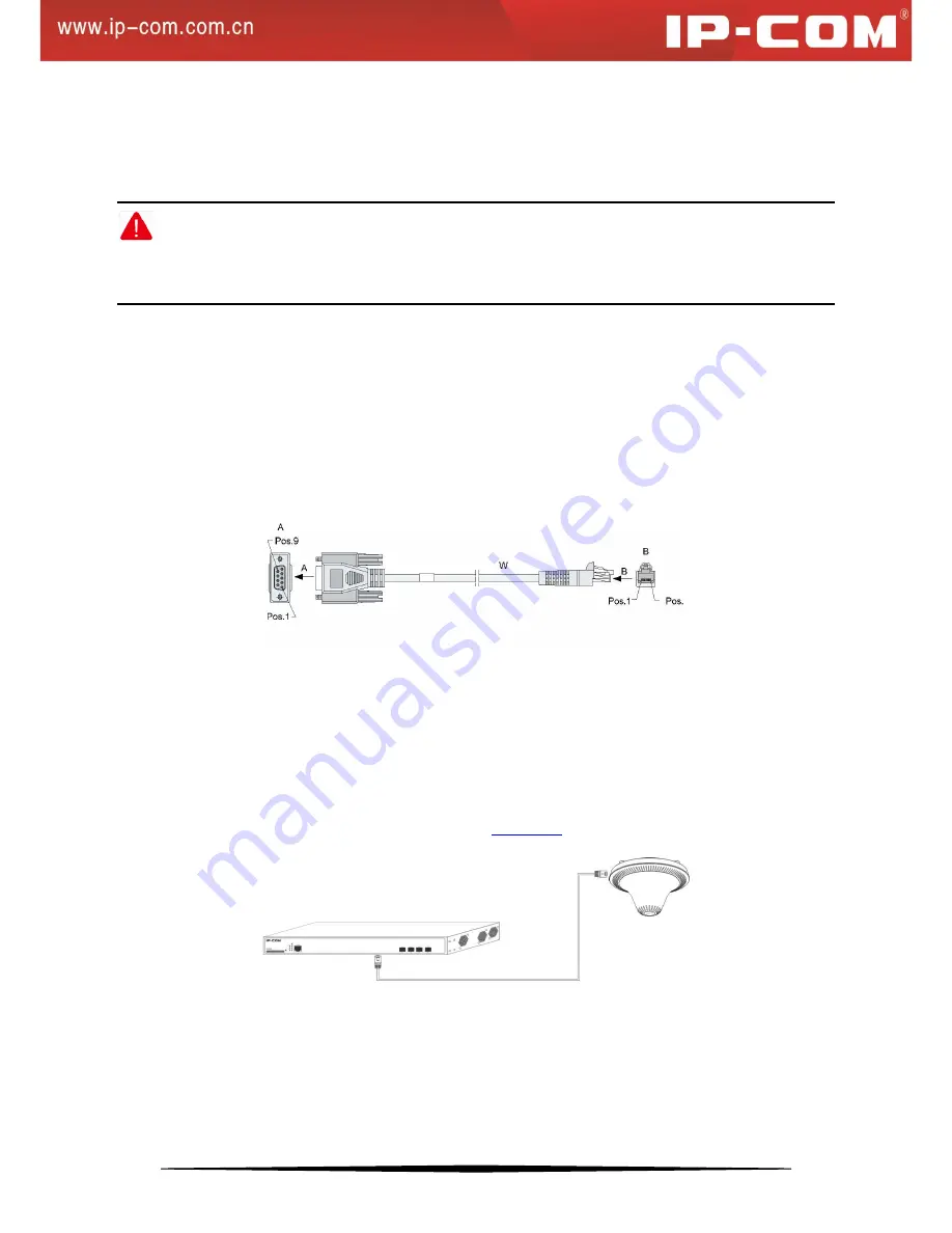
2.5.1 Connecting to Console Port
Follow below steps to connect a PC or terminal to the switch (The terminal can be the emulation program with
RS232 console or a PC. Here take the PC for example):
Connect the DB-9 plug on the console cable to a PC;
Connect the RJ45 connector to the console port on the switch
2.5.2 Connecting to RJ45 ports
The switch provides auto MDI/MDIX feature on each RJ45 ports. PCs or other terminals can simply connect to any
such ports of the switch via CAT.5, CAT.5e, or UTP cables.
1.
Connect one end of the Ethernet cable to the Ethernet interface on the switch and the other end to the remote
device;
2.
Check PoE LED status. For LED status, please refer to
1.4.2 LEDs
.
2.5.3 Connecting to SFP Fiber Combo Ports
The small form-factor pluggable (SFP) module is a compact, hot-pluggable transceiver used for optical signal
transmission. The module bay is a combo port, sharing a connection with an RJ45 port. Being a combo port, only
one type of connection can be active at any given time. For example, both copper and fiber port cannot be used at
Содержание G3224P
Страница 1: ......


