


INSTALLATION INSTRUCTIONS
Gas Furnace: (F/G)9MVE
440 01 4400 03
37
Specifications subject to change without notice.
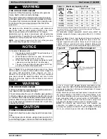
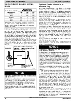
NOTICE
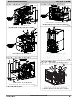
OPTIONAL CONFIGURATION FOR COMBUSTION
AIR INLET PIPE
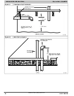
In applications where there is a risk of excessive mois-
ture entering the combustion air inlet pipe, a moisture
trap may be added to the inlet pipe to help prevent
moisture from entering the furnace from the combus-
.
When sizing venting systems, the equivalent length of
the optional inlet pipe moisture trap must be taken into
account.
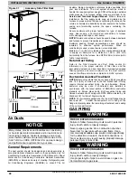
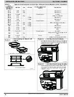
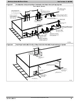
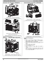
Ventilated Combustion Air Systems
In a ventilated combustion air option, the vent terminates and
discharges the flue products directly to the outdoors similar to a
direct vent system. See
for references to clearances
required by National code authorities.
All air for combustion is piped directly to the furnace from a
space that is well ventilated with outdoor air (such as an attic or
crawl space) and the space is well isolated from the living
space or garage. Combustion air requirements for this option
are the same as the requirements for providing outside air for
combustion for a single pipe vent system. Refer to the “Air For
Combustion and Ventilation Section.”
Provisions for adequate combustion, ventilation, and dilution air
must be provided in accordance with:
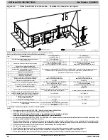
Non-Direct Vent (1-pipe) System
In a non direct-vent (1-pipe) system, all air for combustion is
taken from the area adjacent to furnace, and all flue products
are discharged to outdoor atmosphere. Air for combustion
must be supplied as described in the Air For Combustion and
Ventilation Section. Do not use an abandoned chimney to
supply outside air to the furnace. See
to clearances required by National code authorities.
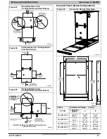
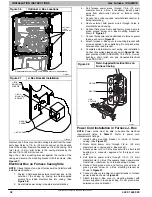
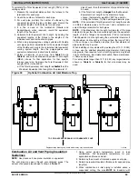
A combustion air pipe to the outdoors is not required for a
single pipe vent system. A 12-in. (304 mm) long pipe with a
2
−
in. (50 mm Nominal Dimension
−
ND) tight radius 90 degree
elbow is required to be attached to the combustion air pipe
adapter on the furnace. (See
) This short inlet air pipe
helps to ensure stable combustion, as well as allow for sound
attenuation. To aid sound attenuation, point the inlet air pipe
away from occupants. An extra elbow and/or five feet (1.5 M) of
pipe may be used to accomplish the sound attenuation
function.
NOTICE
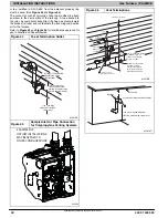
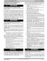
OPTIONAL VENTING BELOW THE FURNACE
The venting system may be positioned below the fur-
nace ONLY IF the factory accessory External Vent
Trap Kit is used. The External Vent Trap Kit is only
approved for PVC/ABS DWV venting systems.
CAREFULLY FOLLOW THE INSTRUCTIONS
PROVIDED WITH THE EXTERNAL VENT TRAP KIT
FOR LAYING OUT THE VENTING SYSTEM AND
THE DRAIN SYSTEM.
The instructions included with
this furnace DO NOT APPLY to vent systems that are
located below the furnace
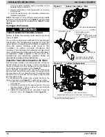
WARNING
!
CARBON MONOXIDE POISONING HAZARD
Failure to follow the instructions outlined in Locating
the Vent Termination for each appliance being placed
into operation could result in carbon monoxide poison-
ing or death.
The instructions included with this furnace DO NOT
APPLY to vent systems that are located below the fur-
nace.
CAREFULLY FOLLOW THE INSTRUCTIONS
PROVIDED WITH THE EXTERNAL VENT TRAP KIT
FOR LAYING OUT THE VENTING SYSTEM AND
THE DRAIN SYSTEM when all or part of the venting
system is placed below the furnace.
Proper configuration of the venting and drain system is
critical when placing all or part of the venting system
below the level of the furnace. VENT GASSES
COULD BE RELEASED FROM THE DRAINAGE
SYSTEM, if the instructions provided with the External
Vent Trap Kit are not followed.


