


INSTALLATION INSTRUCTIONS
Gas Furnace: (F/G)9MVE
440 01 4400 03
43
Specifications subject to change without notice.
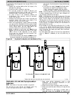
To calculate the Total Equivalent Vent Length (TEVL) of the
venting system:
1. Measure the individual distance from the furnace to the
termination for each pipe.
2. Count the number of elbows for each pipe.
3. For each pipe, multiply the number of elbows by the
equivalent length for the type of elbow used. Record the
equivalent length of all the elbows for each pipe.
4. If a Tee is used on the termination (Alberta and
Saskatchewan, when required), record the equivalent
length of the Tee used.
5. Calculate Total Equivalent Vent Length by adding the
equivalent lengths of the fittings to the lengths of the
individual vent and combustion air pipes.
6. When using polypropylene venting systems with flexible
vent pipes, perform adjustments for the equivalent length
of the flexible vent pipe to the calculated total equivalent
venting system length. See the polypropylene vent
system manufacturer’s instructions for details.
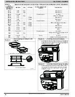
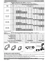
7. Select a diameter of vent pipe from
and
and note the Maximum Equivalent Vent Length
(MEVL) shown for that application for that specific
furnace input size. Compare the Total Equivalent Vent
Length (TEVL) to the MEVL:
a. If the Total Equivalent Vent Length is
shorter
than the
Maximum Equivalent Vent Length for the diameter of
pipe chosen, then that diameter of pipe selected may
be used.
b. If the Total Vent Length is
longer
than the Maximum
Equivalent Vent Length for the diameter of pipe
chosen, that diameter pipe MAY NOT be used for
venting the furnace. Try the next larger diameter pipe.
NOTE
: If the calculated Total Equivalent Vent Lengths results
in different diameter pipes for the vent and combustion air,
select the larger diameter for both pipes.
NOTE
: If the Maximum Vent Length for diameter of the pipe
selected is longer than the measured length and the equivalent
length of all the fittings and terminations (TEVL), recalculate
Total Equivalent Vent Length using the next smaller diameter. If
the Maximum Vent Length is still longer than the longer TEVL
of the vent pipe or combustion air pipe, then that diameter of
pipe selected may be used.
When installing vent systems with pipe lengths of 10 ft. (3.0 M)
or less, use the smallest allowable pipe diameter. Using pipe
size greater than required for short venting systems may result
in loss of efficiency, incomplete combustion, flame disturbance,
or flame sense lockout.
For vent systems longer than 10 ft. (3.0 M), any larger diameter
shown in
or
used.
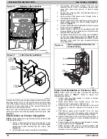
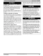
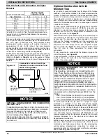
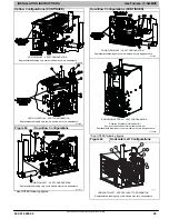
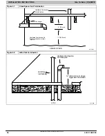
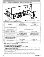
Figure 50
Optional Combustion Air Inlet Moisture Trap
Representative drawing only, some models may vary in appearance.
TO
CODE
−
APPROVED
DRAIN
OR
CONDENSATE
PUMP
L12F028
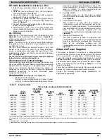
Combustion Air and Vent Piping Insulation
Guidelines
NOTE
: Use closed cell, neoprene insulation or equivalent.
The vent pipe may pass through unconditioned areas. The
amount of exposed pipe allowed is shown in
1. Using winter design temperature (used in load
calculations), find appropriate temperature for your
application and furnace model.
2. Determine the amount of total and exposed vent pipe.
3. Determine required insulation thickness for exposed pipe
length(s).
4. When combustion air inlet piping is installed above a
suspended ceiling, the pipe
MUST
be insulated with


