


INSTALLATION INSTRUCTIONS
Gas Furnace: (F/G)9MVE
440 01 4400 03
13
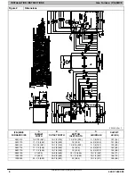
Specifications subject to change without notice.
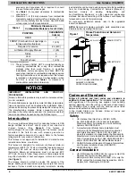
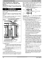
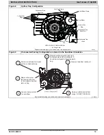
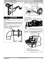
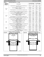
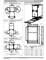
Figure 8
Upflow Trap Configuration
Condensate Trap
Relief Port
Collector Box
Plugs
Pressure Switch
Port
Condensate Trap
Outlet
Condensate Trap
Relief Port
Collector Box
Plug
Vent Elbow
Vent Elbow Clamp
Vent Pipe Clamp
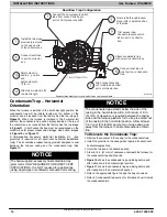
UPFLOW TRAP CONFIGURATION
1 & 2 Stage Units
A11307
Representative drawing only, some models may vary in appearance.
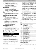
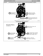
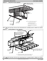
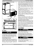
Figure 9
Unconverted Factory Configuration as viewed in the Downflow Orientation
A11587LA
Remove relief tube from relief
port on condensate trap.
Remove the screw
that secures the trap
to the collector box and
remove trap.
Loosen clamp on inlet
to vent elbow.
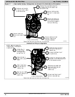
Remove pressure switch tube from
front pressure switch and discard. A
new tube is shipped in the loose parts
bag.
Remove tube from relief port.
Remove middle and bottom
plugs. DO NOT DISCARD.
Representative drawing only, some models may vary in appearance.