


INSTALLATION INSTRUCTIONS
Gas Furnace: (F/G)9MVE
28
440 01 4400 03
Specifications subject to change without notice.
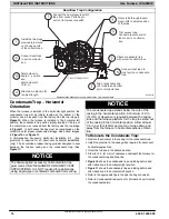
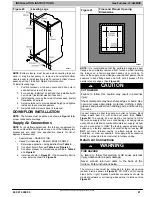
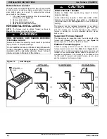
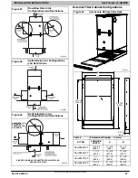
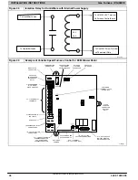
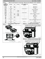
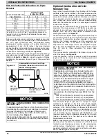
Figure 31
Accessory Side Filter Rack
TABS
FILTER
FRAME
FILTER
DOOR
FURNACE
OPENING
TABS
(TYP.)
OPENING
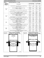
1
1
4”
/
23
⅛
”
(59 cm)
25
⅛
”
(64 cm)
⅜
”
(1 cm)
½
”
(1.3 cm)
2
⅜
”
(6 cm)
17
⅛
”
(43.5 cm)
¾
”
(2 cm)
16
⅛
”
(41 cm)
14
½
”
(37 cm)
L12F023
1
¼
”
(3 cm)
(3 cm)
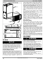
Air Ducts
NOTICE
Many states, provinces and localities are considering
or have implemented standards and/or restrictions on
duct sizing practices, ductwork leakage, and/or duct-
work thermal, airflow and electrical efficiencies. CON-
SULT LOCAL CODE OFFICIALS for ductwork design
and performance requirements in your area.
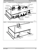
General Requirements
The duct system should be designed and sized according to
accepted national standards such as those published by: Air
Conditioning Contractors Association (ACCA Manual D), Sheet
Metal and Air Conditioning Contractors National Association
(SMACNA) or American Society of Heating, Refrigerating and
Air Conditioning Engineers (ASHRAE) or consult
The Air
Systems Design Guidelines
reference tables available from
your local distributor. The duct system should be sized to
handle the required system design CFM at the design external
static pressure. The furnace airflow rates are provided in the
Service and Technical Support Manual
. When a furnace is
installed so that the supply ducts carry air circulated by the
furnace to areas outside the space containing the furnace, the
return air shall also be handled by duct(s) sealed to the furnace
casing and terminating outside the space containing the
furnace.
Secure ductwork with proper fasteners for type of ductwork
used. Seal supply
−
and return
−
duct connections to furnace
with code approved tape or duct sealer.
NOTE
: Flexible connections should be used between ductwork
and furnace to prevent transmission of vibration.
Ductwork passing through unconditioned space should be
insulated to enhance system performance. When air
conditioning is used, a vapor barrier is recommended.
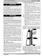
Maintain a 1
−
in. (25 mm) clearance from combustible materials
to supply air ductwork for a distance of 36
−
in. (914 mm)
horizontally from the furnace. See NFPA 90B or local code for
further requirements.
Return Duct Sizing
Refer to the Filter Selection and Duct Sizing section for
information on the proper selection of filter sizes and the
associated ductwork and duct transitions. Improperly designed
filtering systems and return ductwork are the most common
causes of airflow and/or noise complaints in HVAC systems.
Ductwork Acoustical Treatment
NOTE
: Metal duct systems that do not have a 90 degree elbow
and 10 ft. (3 M) of main duct to the first branch take
−
off may
require internal acoustical lining. As an alternative, fibrous
ductwork may be used if constructed and installed in
accordance with the latest edition of SMACNA construction
standard on fibrous glass ducts. Both acoustical lining and
fibrous ductwork shall comply with NFPA 90B as tested by UL
Standard 181 for Class 1 Rigid air ducts.
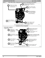
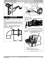
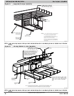
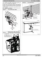
NOTE
: For horizontal applications, the top most flange may be
bent past 90
to allow the evaporator coil to hang on the
flange temporarily while the remaining attachment and sealing
of the coil are performed.
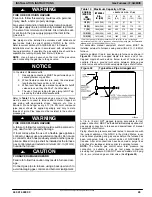
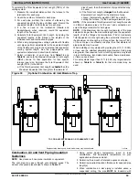
GAS PIPING
WARNING
!
FIRE OR EXPLOSION HAZARD
Failure to follow this warning could result in personal
injury, death, and/or property damage.
Never purge a gas line into a combustion chamber.
Never test for gas leaks with an open flame. Use a
commercially available soap solution made specifically
for the detection of leaks to check all connections. A
fire or explosion may result causing property damage,
personal injury or loss of life.
WARNING
!
FIRE OR EXPLOSION HAZARD
Failure to follow this warning could result in personal
injury, death, and/or property damage.
Use proper length of pipe to avoid stress on gas con-
trol manifold and a gas leak.


