


INSTALLATION INSTRUCTIONS
Gas Furnace: (F/G)9MVE
440 01 4400 03
39
Specifications subject to change without notice.
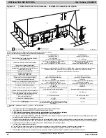
Locating the Vent Termination
General
NOTE
:
Termination Requirements for the Provinces of
Alberta and Saskatchewan are located at the end of this
section.
Combustion
−
air inlet pipe (Direct Vent/2
−
Pipe system only) and
vent pipe must terminate outside structure, either through
sidewall or roof.
For vent termination clearance, references to National codes
are shown in
for Direct Vent/2
−
Pipe system and
for Ventilated Combustion Air/Non
−
direct
Vent/1
−
Pipe system. For exterior termination arrangements,
refer to
for Direct Vent/2
−
for Ventilated Combustion Air/Non
−
Direct/1
−
Pipe system.
Contact Local code authorities for other requirements to and/or
exemptions from the National codes shown in the figures.
Roof termination is often preferred since it is less susceptible to
damage or contamination, is usually located away from
adjacent structures, is less prone to icing conditions, and often
has less visible vent vapors. Sidewall terminations may require
sealing or shielding of building surfaces with a corrosive
resistance material due to the corrosive properties of
combustion products from the vent system, as well as
protection of adjacent structures.
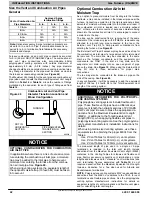
NOTICE
RECOMMENDED SUPPORT FOR VENT
TERMINATIONS
It is recommended that side-wall vent terminations in
excess of 24 inches (0.6 M) or rooftop terminations in
excess of 36 inches (1.0 M) in vertical length be sup-
ported by EITHER the Direct Vent Termination Kit
or by field-supplied brackets or
supports fastened to the structure.
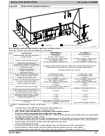
When determining appropriate location for termination, consider
the following guidelines:
1. Comply with all clearance requirements stated in
or
2. Termination or termination kit should be positioned where
vent vapors will not damage plants/shrubs or air
conditioning equipment.
3. Termination or termination kit should be positioned so
that it will not be affected by wind eddy, such as inside
building corners, nor by recirculation of flue gases,
airborne leaves, or light snow.
4. Termination or termination kit should be positioned where
it will not be damaged by or subjected to foreign objects
such as stones, balls, etc.
5. Termination or termination kit should be positioned where
vent vapors are not objectionable.
Direct Vent / 2
−
Pipe System
Direct vent (2
−
pipe) vent and combustion air pipes must
terminate outside the structure. See
for references to
vent clearances required by National code authorities.
Allowable vent and combustion air terminations are shown in
.
!
WARNING
CARBON MONOXIDE POISONING HAZARD
Failure to follow the instructions outlined in Locating
the Vent Termination for each appliance being placed
into operation could result in carbon monoxide
poisoning or death.
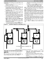
For all venting configurations for this appliance and
other gas appliances placed into operation for the
structure, provisions for adequate combustion,
ventilation, and dilution air must be provided in
accordance with:
U.S.A. Installations:
Section 9.3 NFPA 54/ANSI
Z223.1 1
−
2012, Air for Combustion and Ventilation and
applicable provisions of the local building codes.
Canadian Installations:
Part 8 of
CAN/CSA
−
B149.1
−
10. Venting Systems and Air
Supply for Appliances and all authorities having
jurisdiction.
Ventilated Combustion Air
The vent pipe for a Ventilated Combustion Air System must
terminate outdoors. See
clearances required by National code authorities. Allowable
vent terminations are shown in
. The combustion air
pipe terminates in a well
−
ventilated attic or crawl space. Follow
.
The combustion air pipe cannot terminate in attics or crawl
spaces that use ventilation fans designed to operate in the
heating season. If ventilation fans are present in these areas,
the combustion air pipe must terminate outdoors as a Direct
Vent System.
Non
−
Direct Vent / 1
−
Pipe System
The vent pipe for a Non Direct Vent (1
−
pipe) system must
terminate outdoors. See
for references to vent
clearances required by National code authorities. Allowable
vent terminations are shown in
.
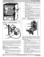
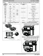
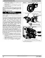
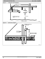
A combustion air inlet pipe to the outdoors is not required for a
Non
−
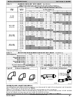
Direct Vent System. A 12
−
in. long section of pipe with a
tight radius 2
−
in. (51 mm) 90 degree elbow is required to be
attached to the furnace. See
. This
short inlet air pipe helps to ensure inlet air pipe away from
occupants. An extra elbow and/or five fee (1.5 M) of pipe may
be used to accomplish the sound attenuation function.
Termination Requirements for the
Provinces of Alberta and Saskatchewan
The Provinces of Alberta and Saskatchewan require a
minimum unobstructed distance of 4 ft. (1.2m) from the
foundation to the property line of the adjacent lot for vent
termination of any appliance with an input over 35,000 btuh. If
there is less than 4 ft. (1.2m) of unobstructed distance to the
property line of the adjacent lot, no type of vent termination is
permitted for appliances with inputs greater than 35,000 btuh.
There are no additional restrictions on unobstructed distances
greater than 8 ft. (2.4m). All single, two-pipe and concentric
vents may be used, providing all other Code and
manufacturer’s requirements in these instructions are adhered
to. Refer to the appropriate
Vent Termination
section above for
locating the vent termination .
If the unobstructed distance from the foundation to the property
line of the adjacent lot is no less than 4 ft. (1.2m) and no
greater than 8 ft. (2.4m), it will be necessary to re-direct the flue
gas plume. In this situation, a concentric vent kit cannot be
used. A 2-pipe termination (or single pipe termination when
permitted) that re-directs the flue gas away by use of an elbow


