


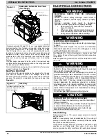


INSTALLATION INSTRUCTIONS
Gas Furnace: (F/G)9MVE
440 01 4400 03
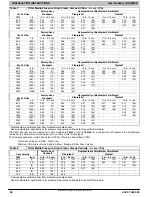
17
Specifications subject to change without notice.
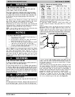
Condensate Drain Connection
CAUTION
!
FROZEN AND BURST WATER PIPE HAZARD
Failure to protect against the risk of freezing may result
in property damage.
Special precautions MUST be made if installing furnace
in an area which may drop below freezing. This can
cause improper operation or damage to equipment. If
furnace environment has the potential of freezing, the
drain trap and drain line must be protected. The use of
accessory drain trap heaters, electric heat tape and/or
RV antifreeze is recommended for these installations.
CAUTION
!
PROPERY DAMAGE HAZARD
Failure to follow this caution may result in burst water
pipes and/or property damage.
If a condensate pump is installed, a plugged condensate
drain or a failed pump may cause the furnace to shut
down. Do not leave the home unattended during freezing
weather without turning off water supply and draining
water pipes or otherwise protecting against the risk of
frozen pipes.
DO NOT trap the drain line in any other location than at the
condensate drain trap supplied with the furnace. If possible, DO
NOT route the drain line where it may freeze. The drain line
must terminate at an inside drain to prevent freezing of the
condensate and possible property damage.
Special precautions MUST be made if installing furnace in an
area which may drop below freezing. This can cause improper
operation or damage to the equipment. If the furnace
environment has the potential of freezing, the drain trap and
drain line must be protected. A self
−
regulating, shielded and
waterproof heat tape rated at 3 to 6 watt per foot (10 to 20 watt
per meter) at 115 volt, 40
°
F (4
°
C) may be used to help provide
freeze protection. Wrap the drain trap and drain line with the
heat tape and secure with appropriate plastic ties. Follow the
heat tape manufacturer’s recommendations. Prime the trap
before furnace operation.
The condensate drain line must be supported and/or secured
per local codes. Supports and clamps should be spaced to
prevent the drain line from sagging or being dislocated from the
furnace or termination point. In the absence of local codes,
consult the edition of the National Standard Plumbing Code
2009, in the US or the National Plumbing Code of Canada
2010 in Canada.
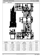
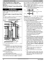
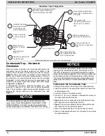
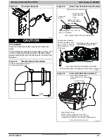
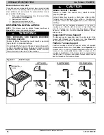
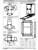
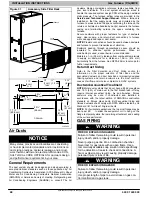
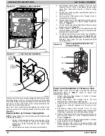
Upflow/Downflow Orientation
In the Upflow or Downflow orientation, the condensate trap is
inside the furnace casing. The condensate drain must be
routed from the trap through the furnace casing. The
condensate drain can be routed through the left or right side of
the casing. (The left or right side is as you are viewing/facing
the furnace from the front.) The furnace condensate drain can
be connected to the indoor coil condensate drain, humidifier or
auxiliary drain traps as shown in
.
NOTE
: On narrower casings, it may be easier to remove the
condensate trap, connect the drain line components and
re-install the condensate trap. Read the steps thoroughly to
familiarize yourself with the required steps.
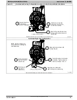
For Right Side Condensate Drain:
1. Remove the 7/8
−
in. knock
−
out from the right side of the
for suggested knockout removal
technique.)
2. Remove the pre
−
formed rubber drain elbow and two
spring clamps from the loose parts bag.
3. Slide a spring clamp 1
−
in. (25 mm) down the plain end
(the end without the formed grommet) of the drain elbow.
4. From inside the casing, insert the formed grommet end
of the elbow through the 7/8
−
in. knockout in the casing.
5. Pull the grommet through the casing from the outside
until it is seated in the knockout
6. Attach the plain end of the drain elbow to the outlet stub
on the drain trap. Secure the drain elbow to the trap with
the spring clamp.
The remaining drain line can be constructed from field supplied
1/2
−
in. CPVC or 3/4
−
in. PVC pipe in compliance with local
building codes. A factory
−
supplied 1/2
−
in. CPVC to 3/4
−
in PVC
adapter is supplied in the loose parts bag for use as required.
7. Install the adapter or connect the 1/2
−
in. CPVC pipe by
sliding a spring clamp over the open end of the grommet
on the outside of the furnace casing.
8. Open the spring clamp and insert the long end of the
adapter of the 1/2
−
in. CPVC pipe into the outlet stub on
the drain elbow.
9. Connect additional condensate piping to a
code
−
approved drain, or to a condensate pump
approved for use with acidic furnace condensate and
compatible with mineral and vegetable oils, such as
canola oil.
Allow at least 1/4
−
in. per foot (20 mm per meter) of slope down
and away from the furnace in horizontal sections of drain line.
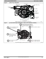
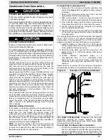
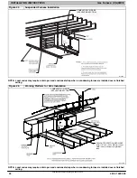
Figure 12
Example of Field Drain Attachment
A13364
TIPS FROM CONTRACTORS:
Contractors have found that
temporarily removing the inducer assembly in upflow
applications while performing the steps below, makes upflow
left
−
side drain connections easier.
For Left Side Condensate Drain Connection:
1. For left side condensate drainage, the drain line is routed
from the condensate trap, behind the inducer (upflow) or
gas valve (downflow) and out through the left side of the
furnace casing. A pre-formed 1/2
−
in. CPVC “Z” pipe is


