


INSTALLATION INSTRUCTIONS
Gas Furnace: (F/G)9MVE
440 01 4400 03
19
Specifications subject to change without notice.
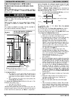
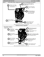
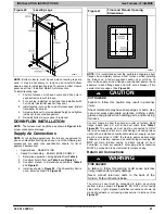
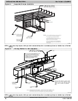
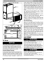
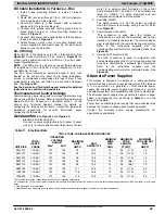
Figure 13
Knockout Removal
L12F019
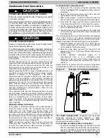
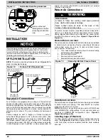
CAUTION
!
CUT HAZARD
Failure to follow this caution may result in personal
injury.
Sheet metal parts may have sharp edges or burrs. Use
care and wear appropriate protective clothing, safety
glasses and gloves when handling parts, and servicing
furnaces.
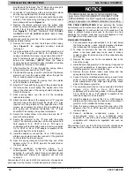
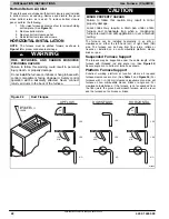
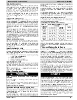
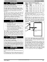
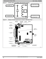
Figure 14
Modify Rubber Drain Elbow
Cut line for left side condensate drain.
Do not discard parts after cutting.
1
−
3/8 in
(35 mm)
L11F089
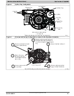
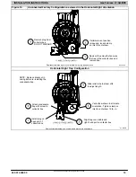
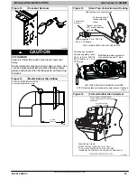
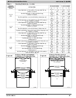
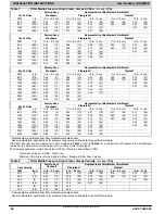
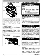
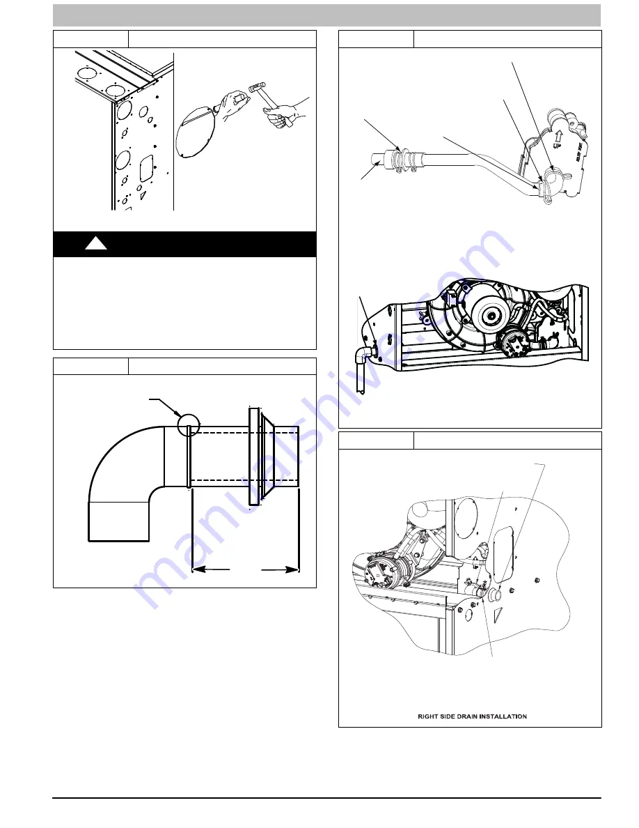
Figure 15
Drain Trap Connection and Routing
s
TRAP, DRAIN ELBOW WITH DISCHARGE PIPE
Attach elbow to condensate trap
Cut formed end off
condensate drain
elbow
Connect short end
of “Z” pipe to modified
drain elbow
Factory supplied 1/2
−
in. CPVC to
3/4
−
in. PVC adapter
LEFT SIDE DRAIN ROUTED BEHIND INDUCER
Formed end of grommet
Open spring clamp. Insert
1/2
−
in. to 3/4
−
in. CPVC to
PVC adapter or 1/2
−
in.
CPVC pipe
Modified drain elbow connect to
condensate trap and “Z” pipe
Formed end of
grommet
NOTE: Remove Inducer Housing for easier access, if desired.
L12F015
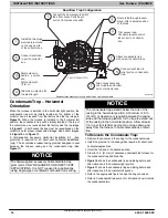
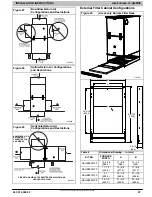
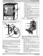
Figure 16
Formed Rubber Drain Grommet
L12F022
INSTALL CLAMPS ON DRAIN ELBOW
ATTACH DRAIN ELBOW TO CONDENSATE
DRAIN TRAP
PULL DRAIN STUB
THROUGH CASING
OPEN SPRING CLAMP
INSERT FACTORY
−
SUPPLIED 1/2
−
IN. CPVC
TO 3/4
−
IN. PVC ADAPTER OR 1/2
−
IN. CPVC PIPE
*CLAMP MAY BE LOCATED ON OUTSIDE OF DRAIN ELBOW