


INSTALLATION INSTRUCTIONS
Gas Furnace: (F/G)9MVE
32
440 01 4400 03
Specifications subject to change without notice.
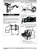
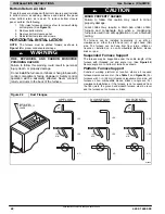
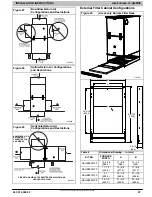
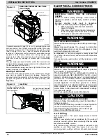
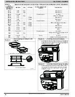
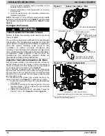
Figure 36
Optional J
−
Box Locations
Representative drawing only, some models may vary in appearance.
L12F024
OPTIONAL
J
−
BOX
LOCATIONS
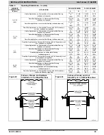
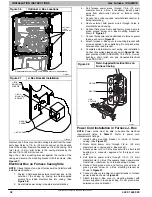
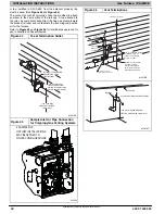
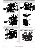
Figure 37
J
−
Box Bracket Installation
L12F025
J
−
BOX
MOUNTING
SCREWS
J
−
BOX
MOUNTING
BRACKET
GROUND
SCREW
J
−
BOX COVER
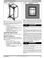
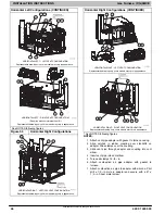
Remove the J
−
Box cover and mounting bracket from the loose
parts bag. Select a 7/8
−
in. (22 mm) knock-out on the desired
side of the casing. Remove the knock-out from the casing. Drill
two 1/8
−
in. (3 mm) pilot holes in the casing dimples by the
desired 7/8
−
in. (22 mm) knock-out.
Align the J
−
Box mounting bracket against the inside of the
casing and secure the mounting bracket with the screws. (See
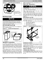
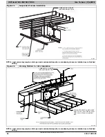
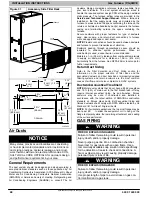
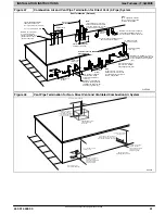
Electrical Box on Furnace Casing Side
NOTE
: Check that duct on side of furnace will not interfere with
installed electrical box.
1. Fasten a field-supplied external electrical box to the
outside of the casing by driving two field-supplied
screws from inside electrical box into casing. (See
2. Route field power wiring into external electrical box.
3. Pull furnace power wires through 1/2-in. (12 mm)
diameter hole in J
−
Box. If necessary, loosen power
wires from strain
−
relief wire-tie on furnace wiring
harness.
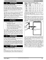
4. Connect any code required external disconnect(s) to
field power wiring.
5. Route external field power wires through holes in
electrical box and casing.
6. Connect field ground wire and factory ground wire to
green ground screw on J
−
Box mounting bracket as
shown in
7. Connect field power and neutral leads to furnace power
leads. as shown in
8. Attach furnace J
−
Box cover to mounting bracket with
screws supplied in loose parts bag. Do not pinch wires
between cover and bracket.
9. Complete external disconnect wiring and installation.
Connect line voltage leads as shown in
best practices (NEC) ANSI/NFPA 70 in U.S.A. for wire
bushings, strain relief, etc., and Canadian Electrical
Code CSA C22.1.
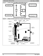
Figure 38
Field
−
Supplied Electrical Box on
Furnace Casing
A10141
GROUND
NEUTRAL
LINE
VOLTAGE
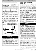
Power Cord Installation in Furnace J
−
Box
NOTE:
Power cords must be able to handle the electrical
requirements listed in
. Refer to power cord
manufacturer’s listings.
1. Install J
−
Box mounting bracket to inside of furnace
)
2. Route listed power cord through 7/8
−
in. (22 mm)
diameter hole in casing and J
−
Box bracket.
3. Secure power cord to J
−
Box bracket with a strain relief
bushing or a connector approved for the type of cord
used.
4. Pull furnace power wires through 1/2
−
in. (12 mm)
diameter hole in J
−
Box. If necessary, loosen power wires
from strain—relief wire
−
tie on furnace wiring harness.
5. Connect field ground wire and factory ground wire to
green ground screw on J
−
Box mounting bracket as
shown in
6. Connect power cord power and neutral leads to furnace
7. Attach furnace J
−
Box cover to mounting bracket with
screws supplied in loose parts bag. Do not pinch wires
between cover and bracket.