


6
Technical Data
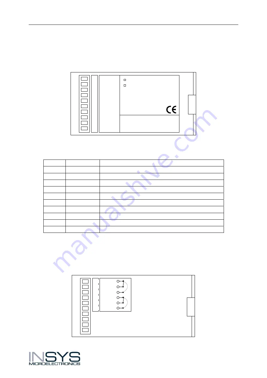
3.3 Terminal
Layout
The terminals are designed as screw terminals and are located on the top and bottom of
the cover.
View of the cover top
1
2
4
5
6
7
8
9
10
3
INSYS WLAN serial
INSYS WLAN bridge
INSYS MICROELECTRONICS GmbH
Internet: www.insys-tec.de
Sales: [email protected]
Support: [email protected]
GND
50...80 VDC
GND
GND
Reset
GND
Input 1
Input 2
GND
10...60 VDC
Layout of the terminals on the cover top
Terminal Labeling
Description
1 GND
Ground
2
50...80 VDC
Supply voltage input 50 – 80 V DC (optional)
3
10...60 VDC
Supply voltage input 10 – 60 V DC
4 GND
Ground
5 GND
Ground
6 Reset Reset
input
7 GND
Ground
8
Input 1
Digital input 1
9
Input 2
Digital input 2
10 GND
Ground
Attention!
For series devices, the supply voltage input for the range 50 – 80 V DC at
terminal 2 is not equipped. If required, devices with this supply voltage
input may be ordered.
View of the cover bottom
OUT 1-NC
OUT 1
OUT 2-NC
OUT 2
OUT 2-NO
OUT 1-NO
11
12
14
15
16
13
version 1.01 / 10.04
Содержание WLAN bridge
Страница 1: ...Operating Manual INSYS WLAN bridge WLAN serial Version 1 01 10 04 ...
Страница 6: ......


