9.0 OPERATING INSTRUCTIONS
TS1A–13A
http://air.irco.com
38
9.3
DISPLAY SCREEN
The display screen has four basic graphic representations. These are
the evaporator temperature and relative humidity indicator, local
ambient area temperature, the operational status, and the dryer system
operating schematic.
The evaporator temperature shows a relative scale of its coldest air
temperature, which relates closely to dew point temperature. Green
indicates a good dew point, yellow indicates a cautionary high dew
point, and red indicates a high dew point.
When toggled to, this same scale illustrates an approximate relative
humidity of the compressed air at the discharge of the dryer.
Calculation of this value is based on local ambient air temperature,
typical performance parameters of Ingersoll Rand air compressors
when operating in the same ambient temperature, and the evaporator
temperature.
The ambient temperature illustrates the relative temperature of the air
that the dryer is exposed to. When the dryer operates in the green
section, it is operating in an environment that should not affect the
performance of a properly sized dryer. When operating in the yellow
section, the ambient temperature may start to affect dryer
performance. When operating in the red section, the dryer may be
approaching or has exceeded the maximum allowable ambient
operating temperature.
The Operation status contains four pictographics. The “lightning
bolt”(8) indicates the electrical panel has power provided to it, the
“running man”(9) indicates the refrigerant compressor is running, the
“star”(12) indicates the dryer is running in the optional energy savings
mode, and the “wrench”(13) indicates the regular interval for
preventative maintenance has been reached.
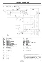
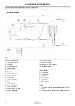
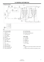
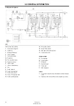
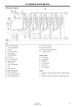
The dryer system operational schematic contains LED’s to indicate if
a system warning (yellow LED) or alarm shut down (red LED) has
occurred and from which primary component.
9.4 OPERATOR
SETPOINTS
Listing 1.0 Entering Setpoint Menus
S
USER SETPOINTS
[RESET] [TOGGLE] [TOGGLE]
(KEY SEQUENCE MUST BE DONE WITHIN 3 SECONDS TO
ENTER SETPOINT MODE)
Once the setpoint menu is entered the two bar graphs on the front of
the controller will be used to show setpoint number and value. The
Evaporator/%RH bar graph will indicate setpoint function and the
Ambient temperature bar graph will indicate setpoint number. To
navigate through the setpoint menu the TOGGLE, RESET and STOP
keys will be used. The function of the keys is illustrated in Listing 1.1.
Listing 1.1 Setpoint Navigation
S
TOGGLE
USED TO ITERATE THROUGH SETPOINT NUMBERS AND
CHANGE VALUES.
S
RESET
USED TO INITIATE A DATA INPUT SESSION AND TO SAVE
DATA INPUT.
S
STOP
USED AS A LEVEL BACKOUT MECHANISM AND SETPOINT
MENU EXIT.
Listing 1.2 Menu Functions
S
NAVIGATION
Use the TOGGLE key to iterate through the setpoint functions.
S
CHANGING SETPOINT DATA
When ready to make a set point value change use the RESET key
to initiate a value input session. Then use the TOGGLE key to
increment the setpoint value NOTE: setpoint value and set point
function will roll around once the maximum function or value is
reached.
Once the desired value is entered use the RESET key to save the
newly entered value. The controller will flash the data to confirm
the new value save. Then the controller will back out to the
setpoint scrolling state and you may continue to scroll through
the setpoint functions.
S
EXITING SETPOINTS AND MENUS
The STOP key is used as a level back out function. It will always
back out one level from where ever one is in a setpoint menu. For
example if one is in a setpoint menu and scrolling through all the
setpoint functions and presses the STOP key, the controller will
exit the setpoint menu. Another example is if one is changing a
setpoint value and decides its not the setpoint that was intended
to be changed, one can just press the STOP key and the controller
will back out to the setpoint scrolling state of the setpoint menu.
S
AUTOMATIC MENU EXIT
If the controller does not receive any key presses within a 30
second time span, it will back out of the current setpoint menu.
Содержание TS10A
Страница 2: ......
Страница 10: ...5 0 SAFETY TS1A 13A http air irco com 8 5 3 TEXT DECALS NORTH AMERICA ...
Страница 50: ......
Страница 52: ......
Страница 60: ...5 0 SECURITE TS1A 13A http air irco com 8 5 3 DÉCALCOMANIES DES TEXTES AMÉRIQUE DU NORD ...
Страница 101: ......
Страница 102: ......
Страница 104: ......
Страница 112: ...5 0 SEGURANÇA TS1A 13A http air irco com 8 5 3 AUTOCOLANTES DE TEXTO AMÉRICA DO NORTE ...
Страница 152: ......
Страница 161: ...5 0 SEGURIDAD TS1A 13A http air irco com 8 5 3 CALCOMANÍAS DE TEXTO AMÉRICA DEL NORTE ...
Страница 203: ......
Страница 204: ......


