28/126
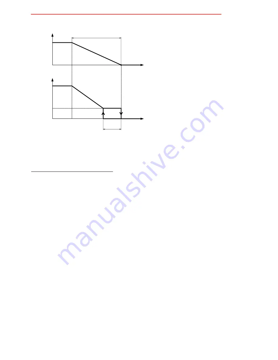
• EC motor automatic speed control logic with 0..10 V modulating outputs
We take the example of control in heating mode.
Temp.
BHS
(
I07
)
ECM speed 1
% opening valve
Fan
ECM speed 3
PBH
(
I22
)
(
I31
)
0%
100%
100
0
Output valve
AO1
The graph refers to heating mode.
Set the EC motor parameters as follows:
- Set the voltage corresponding to the minimum EC motor speed with parameter
I29
.
- Set the voltage corresponding to the maximum EC motor speed with parameter
I30
.
- Set parameters
I32
,
I33
,
I34
for speeds 1, 2, 3 respectively.
Example: if
I29
=1V,
I30
=8V and
I32
=10%, speed 1 corresponds to 1.7V → [
I32
x (
I30
-
I29
) +
I29
]
Automatic speed control is linear over the range of speeds 1 to 3, while manual control simply sets a given speed (see
“4. Quick access parameter setting” page 8
).
To set speed 1 to the minimum EC motor speed, set
I32
to 0.
To set speed 3 to the maximum EC motor speed, set
I34
to 100.
To set speed 2 to the midpoint between speeds 1 and 3, set
I33
to 50.
- Set parameter
I31
to determine the point at which the motor starts in relation to the valve's opening percentage.
This enables the fan to start when water is already circulating in the fancoil coil.
Example: if
I31
=5%, the motor starts when the valve's modulating output exceeds 0.5V → [
I31
*10 V]. The fan stops
when the valve closes.
N.B.: parameters
I24
,
I25
and
I26
are not used in this application.


