


E081101X 14/11/08
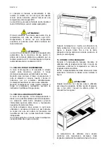
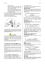
means are suitable for the ironer movimentation.
In order to remove the ironer from the pallet, pass
the forks of the forklift truck under the ironer
collecting tray (avoiding scratch on the machine
paint).
Lift the ironer, take off the pallet and position the
machine.
ATTENTION!
The pallet do not have to be used as usual
machine support! The machine must always be
removed from the pallet and position as described
in the relative paragraph.
ATTENTION!
Ironer movement with forklift truck must be done
only by trained and competent operators.
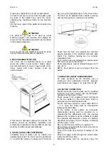
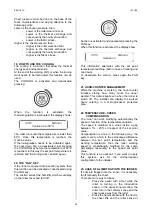
5. MACHINE IDENTIFICATION
The ironer can be identified thanks to a label
where are written: serial number, model, power
and technical data. In case of spare parts order,
ironer model and serial number must be
communicated.
If this label is damaged, removed or absent, the
machine cannot be identified; installation and
maintenance operations become difficult and the
warranty condition expire automatically.
6. INSTALLATION AND POSITIONING
Installation must be taken over by trained and
qualified personnel. The ironer must be positioned
in a perfect flat surface in steady and horizontal
way using the adjustable feet on the ironer sides.
The feet can be adjusted from outside, screwing
and unscrewing them, until the iron is laid flat.
Check that the floor can support the machine
weight indicated in the attached technical data
sheet. The machine loading can be consider
completely static.
For a correct use and maintenance, please leave
500 mm room around the ironer.
Room temperature must be icluded b5°C
and +40°C.
NOTE: the machine must be removed from the
pallet!
7. INDICATION ABOUT NOISE EMISSION
Air noise produced by the machine, give a
continuous and ponderated acoustic pressure
level; reference is category “A”, lower than 70 dB.
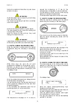
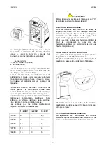
8. ELECTRIC CONNECTION
Electric connection must be take over by qualified
technician and must comply with the European,
national and local rules in force.
Check always if the supplied tension correspond
to the one written on the ironer label, which is
positioned on the machine back side.
For the machine connection, use a cable H05 VV
– F or more; the cable must be dimensioned
following the label data.
At the bottom of the system an omni-polar
disconnection device must be provided (i.e. a
magneto-thermal differential unit); the opening
between the contacts must be suitable to enable
the complete disconnection in case of condition
described by category III and, anyway, complying
with the rules in force.
Be sure that the main switch is in position “0”.
Using the key supplied with the ironer documents,
open the left side door.
Take off the side door making it rotating on the
base.
Pass the supply cable through the cable holder
inside the left ironer side.
Electrical supply must be executing using the
21