IDEAL INDUSTRIES SignalTEK II Скачать руководство пользователя страница 14


156810 Iss 1 


SignalTEK II 

Page 14 


User Guide 


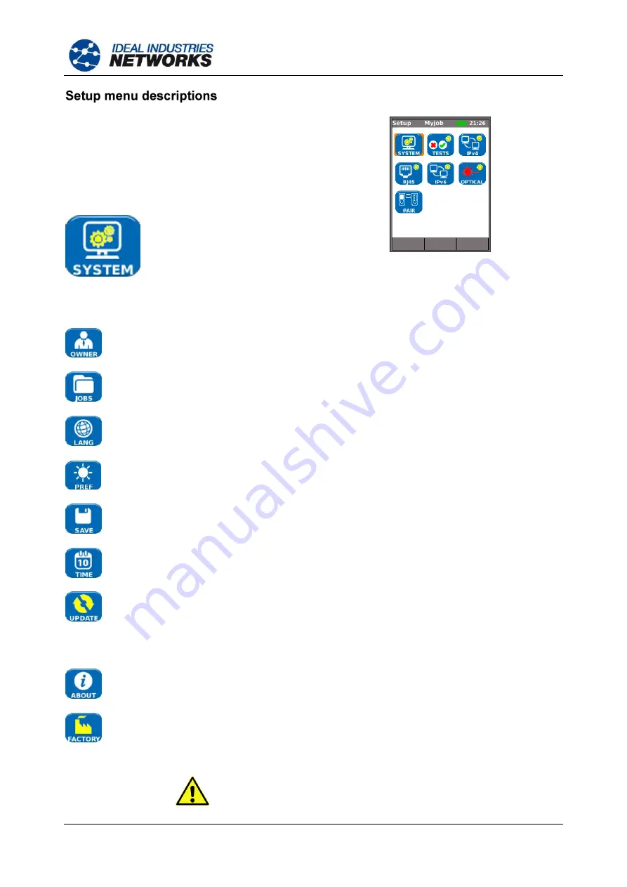
From  the  home  screen,  press  the  soft  key  SETUP 
(F3)  to  display  the  Setup  menu  shown  in  Fig  14.  
The settings for all tests, functions and preferences 
can be changed and saved from here. 

Selecting  any  of  the  seven  icons  will  produce  the 
options that follow: 


Fig 14 

Highlight the System icon and press ENTER to access the settings and preferences listed below: 


Enter  your  name or  your compan

y’s name, address and phone number(s).  The details 

stored here will appear on all reports exported via a USB key. 


This  option  enables  you  to  manage  Jobs  as  follows:    Create  new  Jobs.    View,  edit  or 
delete  existing  Jobs.    Save  Jobs  to a  USB  key.  The 

‘Activate’ icon selects the Job you 

require to be active.  Se

Jobs

 for a full description. 


Sets  the  language  for  the  tester.    The  on-screen  display,  and  the  exported  results  and 
reports will appear in the selected language. 


Sets  the  power  saving  options,  the  preferred  units  of  length  and  the  date  and  time 
formats. 


Export or import setup information to/from a USB stick.  Use this function when you wish 
to copy setup information from one tester to another. 


Sets  the  current  date  and  time.    Note  that  the  date  and  time  are  recorded  against  test 
results  and  will  appear  on  exported  reports.    The  internal  clock  is  autonomous  of  the 
power module or battery pack for up to one day. 


For the Near-End Unit this menu item facilitates software updates downloaded from the 
IDEAL  website  and  saved  to  a  USB  key.    Select  the  update  icon  and  follow  the  on-
screen instructions.  To update the Remote Unit: with unit switched OFF, insert USB key 
and  then  PRESS  and  HOLD  the  AUTOTEST  key  while  switching  on  the  unit. 
The  LED’s  will  illuminate  in  sequence  indicating  that  a  software  update  is  in  progress.  
The unit reboots when the update is complete. 


Provides model, software, hardware and firmware information. 


Provides  the  option  to  return  all  settings  to  the  factory  default.    The  Near-End  and 
Remote Unit must be paired after resetting to factory default.  Refer to PAIR on 

page 17

. 


A FACTORY RESET WILL REMOVE ALL STORED DATA


AND PAIRING INFORMATION


FROM THE TESTER


www.vemco.pl

Содержание SignalTEK II

Страница 1: ...SignalTEK II User Guide 156810 issue 1 w w w v e m c o p l ...

Страница 2: ... Ltd pursues a policy of continual product improvement and reserves the right to alter without notice the specification design price or conditions of supply of any product or service All rights reserved Publication ref 156810 Issue 1 Issue 1 04 12 Applies to software revision 1 0 0 onwards IDEAL INDUSTRIES LTD Stokenchurch House Oxford Road Stokenchurch High Wycombe Buckinghamshire HP14 3SX UK UK ...

Страница 3: ...12 Replaceable insert RJ 45 socket 12 Setup 13 Setup menu descriptions 14 Supported SFP Transceivers 17 Tests modes 18 Cable mode 18 Ethernet mode 18 Tests run setup and save 19 Tests menu description Cable mode 20 Wiremap 20 Tone 23 Autotest 23 Tests menu description Ethernet mode 24 Cable performance 24 PoE 25 Blink 25 Ping4 and Ping6 26 TRoute4 and TRoute6 26 Netscan 27 VoIP 28 Web 29 Video 29 ...

Страница 4: ...are both connected to the same network the Near End Unit will find the Remote Unit that it is uniquely paired with and not any other SignalTEK II Remote Unit that may be connected to the same network The Near End unit may be used as a stand alone device for wiremap testing copper network cables When both units are directly connected by a cable wiremap and cable performance tests can be run When th...

Страница 5: ...spose of both complete units in accordance with local environmental regulations When using SignalTEK II always take basic safety precautions to reduce the risk of fire electric shock and injury to persons These include the following When connecting to the line special care must be taken as high voltages may be present on the line and there may be a danger of electrocution Avoid using SignalTEK II ...

Страница 6: ...th the SignalTEK II either unit switched ON or OFF To recharge the power module connect the supplied power adaptor to the DC inlet For convenience the power module may be removed from or left attached to the unit for charging The Power LED next to the DC inlet glows green to show that the battery is being charged and flashes green to show that it is not being charged The Near End Unit s power modu...

Страница 7: ...erences are selected from SETUP SYSTEM PREF Auto Off can be Disabled unit remains ON indefinitely or set to switch the unit OFF after three 10 or 30 minutes of inactivity The backlight can be set to Always On or to dim to 50 brightness after three minutes of inactivity Note that when mains power is connected the display is always on full brightness and the unit remains ON indefinitely Remote Unit ...

Страница 8: ... SFP 12 ON OFF button 20 100 Mb s line rate LED 5 1 Optical activity LED 13 2 Power module 21 10 Mb s line rate LED 6 1 Optical link LED 14 2 Charger LED 22 Remote Autotest button 7 USB port 15 2 DC in connector 23 Power LED 8 LCD color display 16 Autotest button 1 Fig 4 items 4 5 6 SignalTEK II FO only 2 Fig 4 item 13 shows optional power module Note The top bottom and left hand side of both unit...

Страница 9: ...isplay Their function changes and is dependent on the screen currently shown on the display Fig 6 When you navigate to and select a field that requires a value or text to be entered such as a customer s name or a URL a QWERTY keyboard will be shown on the display Fig 6 All data is entered using the QWERTY keyboard Move the key that is highlighted on the keyboard using the tester s cursor keys ENTE...

Страница 10: ... key DETECT F1 to display all options available from the Cable mode screen When an Active Remote is connected it will be shown on screen Fig 7 and its identification number displayed For a full description of these options see Tests menu description Cable mode Fig 7 Ethernet Fig 8 Ethernet mode is used for a range of IP and performance tests There are three ways to connect in Ethernet mode 1 When ...

Страница 11: ...own The IPv4 and IPv6 addresses assigned to the tester are displayed when available Fig 9 Fig 10 3 When both the Near End Unit and Remote Unit are connected to an active network using copper or fiber cables press the soft key DETECT F1 to display all options available Fig 10 IP tests and performance tests can be run For a full description of these options see Tests menu description Ethernet mode p...

Страница 12: ... Fig 11 Replaceable insert RJ 45 socket To replace a damaged or worn RJ 45 socket insert proceed as follows Equipment required Kit IDEAL part number 150058 includes Tool x1 and Replacement Insert x10 Switch the SignalTEK II OFF Connect the tool to the socket insert that is to be replaced Note the orientation of the insert within the socket and carefully remove it using the tool Install the new ins...

Страница 13: ...All user defined settings and preferences of the SignalTEK II are set from the SETUP menu A map of the SETUP menu is shown at Fig 13 and a description of the available settings and preferences is found on pages 14 to 17 Fig 13 w w w v e m c o p l ...

Страница 14: ...and time formats Export or import setup information to from a USB stick Use this function when you wish to copy setup information from one tester to another Sets the current date and time Note that the date and time are recorded against test results and will appear on exported reports The internal clock is autonomous of the power module or battery pack for up to one day For the Near End Unit this ...

Страница 15: ... Length Number of bytes in Ping frame payload 8 to 1000 bytes Set the target URL Numerical address select from up to 10 targets stored in the v4 TARGET look up table or edit the currently displayed URL Maximum number of hops 2 to 100 Timeout Abort timeout for any hop 2 to 30 secs Use a short timeout to reduce test time or a long timeout to reach remote internet locations Protocol ICMP or UDP as re...

Страница 16: ...us calls on the network 1 to 10 000 Threshold Frames Enter the number of errored frames acceptable 0 to 99 Duration Set test duration from 1 second up to 24 hrs No of sessions Set expected number of simultaneous sessions on the network 1 to 500 Threshold Frames Enter the number of errored frames acceptable 0 to 99 Duration Set test duration from 1 second up to 24 hrs Definition Set to HD or SD No ...

Страница 17: ...kew data are displayed for information only Provides the information that follows on the SFP connected to the Optical port Status Available or Not Fitted Vendor Part number Rx Power µW Tx Power µW See Supported SFP Transceivers below When first supplied the Near End and Remote units are paired When a different or replacement Remote Unit is used or the Near End Unit has been RESET to factory defaul...

Страница 18: ...s that are dependent on the services detected by the Near End Unit All available tests are illustrated in the three menu maps that follow 1 When a SignalTEK II Remote Unit is directly connected but no active network is detected the home screen information bar will read Ethernet When the TESTS icon is selected the Ethernet tests shown in the menu map at Fig 16 are available Fig 16 Tests menu map Et...

Страница 19: ... in the display s information bar Indicates test has not been run and that the tester is ready Will be displayed if the test is aborted or when a test has been run and a fault detected or a network is unknown or unreachable Indicates test is in progress This symbol is also displayed while the tester is detecting a port Indicates a test has been run with no faults detected When a test is complete t...

Страница 20: ...t will be run on the cable currently connected to the tester s RJ45 port The settings used for the test will be those that have been preset via the setup menu SETUP TESTS WIRETEST WIREMAP After the test has been run the display will show a graphical interpretation of the result Fig 21 and an indication of the distance to the fault or the length of the cable In addition a FAULT icon and a SAVE soft...

Страница 21: ... Fig 24 Fig 23 Fig 24 The wiremap tests may be run with no termination open or with an Active Remote termination When connected an image of an Active Remote will be shown on the display and its type identified After a test has been run the length of the cable is displayed range up to 100m 330ft With an open termination the possible faults detected are Fig 25 Open circuit by pair Fig 26 Short circu...

Страница 22: ...shorts Fig 32 Remote shorts As with the result of the Crossover fault shown in Fig 21 and Fig 22 all wiremap test results are displayed as a graphic that includes the FAULT icon When the icon is selected the faults are presented as a list The indications that follow appear on the Active Remote device Flashing green LED Test Passed Flashing red LED Test Failed Amber LED DC voltage greater than 12 V...

Страница 23: ...s the soft key APPLY F2 for your changes to take effect Autotest Fig 34 SignalTEK II can be set up to run a predefined range of tests when the yellow Autotest button is pressed on either the Near End or Remote Unit The range of tests is set from SETUP TESTS AUTOTEST by ticking the check boxes next to your choice Fig 34 Press the soft key APPLY F2 for your changes to take effect Fig 35 When an Auto...

Страница 24: ...here they are checked and counted Fig 38 shows the result screen of a successful cable test Frame Size which is fixed is stated for information Tx states the number of frames transmitted the associated green indicator bar confirms that 100 of the frames were sent As the frame size and fill is fixed the number of frames transmitted is dependent on the duration of the test only Rx states the number ...

Страница 25: ...e power available at the connected port SignalTEK II identifies which pairs are carrying power and displays the voltage V current mA and power W The PoE test result screen at Fig 42 shows that pair one and two and pair three and six are carrying 11 Watts The port tested is capable of powering devices that require upto 11 Watts The test is PASSED because the power available is the minimum power val...

Страница 26: ...99999 Delay Round trip delay in ms between transmitting Ping and receiving response Displayed as Minimum Average and Maximum Fig 43 TRoute4 and TRoute6 Trace Route will display the route and measure transit delays of frames across an IP network Press the soft key SETUP F3 to enter the target or select one from the v4 or v6 TARGET look up table and to view or amend the test settings Select an indiv...

Страница 27: ...0 Iss 1 User Guide Page 27 Netscan Netscan will report the number of IPv4 hosts and IPv6 hosts detected within the scan range Press the soft key SETUP F3 to adjust the scan settings if required Fig 45 w w w v e m c o p l ...

Страница 28: ... which may interfere with other network users CONTINUE YES NO Select YES to continue with the test and not display the warning again until the next power cycle Select NO to not continue with test and display the warning again before another test is run Performance tests are as follows Fig 46 Fig 47 Fig 48 IP Tests Fig 49 Performance Tests VoIP Fig 50 shows the result screen of a successful VoIP te...

Страница 29: ...tered and the definition chosen at set up Tx states the number of frames transmitted the green indicator bar confirms that 100 of the frames were sent Rx states the number of frames received the green indicator bar confirms that 100 of the transmitted frames were received As all transmitted frames were received Error states 0 and its associated indicator bar remains uncolored and shows 0 Fig 52 CC...

Страница 30: ... saved by pressing the soft key SAVE F2 The Save Result screen is displayed From here you may choose which Job to save the test s to and the prefix and serial number of the Result If you do not choose SignalTEK II defaults to the active Job and assigns the next serial number The structure in which Jobs Results and test results are stored is shown in Fig 54 Fig 54 Example of Job storage structure W...

Страница 31: ...n Change the active Job In the example of a Job List screen shown at Fig 55 the active Job is Acme as indicated on the display s information bar To change the active Job scroll to the Job required e g My Job and press the soft key OPTIONS F2 the display will show the Options screen Fig 56 Highlight the ACTIVATE icon and press ENTER Fig 56 Options screen The display will show a dialogue stating MyJ...

Страница 32: ...ive Job Amend any details of an existing Job Press the soft key APPLY F2 to save the changes Delete a Job and all its associated Results When DELETE is selected the dialogue Are you sure you want to delete Job will appear ONCE DELETED A JOB CANNOT BE RESTORED Selects the Job to be currently active All test results are saved to the active Job Full details of this function are described on page 31 W...

Страница 33: ...t a USB key into the SignalTEK II USB port From the home screen select the JOBS icon The display will show the Job List screen Highlight the Job required and press ENTER The display shows all Results contained within the Job Highlight the Result you require and press the soft key TO USB F3 The dialogue Result saved to USB appears Test results and statistics are now saved on the USB key and can be ...

Страница 34: ... Unit Network Test Connected to an active network Connector type SFP socket Location Left hand side System Ports USB Used for Software Update Results transfer Class Host Connector type A USB type 1 1 Location Top Power Used for Battery charging Mains powering via adaptor Connector type 2 5mm pin power jack Polarity Centre pin positive Voltage 12v Current 2 amp Location Bottom of power module Not p...

Страница 35: ...on of charging status Green Battery is charging Off with charger connected Battery is charging Green flashing Battery is not being charged Color Green Location Bottom of Power module Not present in alkaline battery pack RJ45 Link LED Use ON indicates link UP Location Adjacent to RJ45 socket nearest top of tester Color Green RJ45 Activity LED Use Flashing indicates link activity Location Adjacent t...

Страница 36: ...ve remote 1 12 detected Link Mode Tests Active network detected but no Remote Unit IPv4 Ping IPv6 Ping Traceroute v4 Traceroute v6 Netscan PoE PoE Load Hub Blink Auto IPv4 Ping IPv6 Ping Traceroute v4 Traceroute v6 Netscan PoE PoE Load Remote Mode Tests Remote Unit detected but no network Double ended Wiremap Cable Performance Auto Double ended Wiremap Cable Performance Link Remote Mode Tests Remo...

Страница 37: ...etected Services PoE PoE 802 3af at Not Cisco pre standard ISDN PBX Unknown Optical Supported SFPs The following SFP types are supported Use of other types of SFP is possible but correct operation is not guaranteed SFP Type SX Manufacturer Part Avago AFBR 5705PZ Apac LM28 C3S TI N DD Speed 1Gb s Fiber Type Multimode Wavelength 850nm Connector Type LC Duplex SFP Type LX Manufacturer Part Avago AFCT...

Страница 38: ...e Active remote 1 12 detected Link Mode Tests Active network detected but no Remote Unit IPv4 Ping IPv6 Ping Traceroute v4 Traceroute v6 Netscan Hub Blink Auto IPv4 Ping IPv6 Ping Traceroute v4 Traceroute v6 Netscan Remote Mode Tests Remote Unit detected but no network Cable Performance Auto Cable Performance Link Remote Mode Tests Remote Unit detected through a network device VoIP Performance Web...

Страница 39: ... icon Active Remote 1 12 Remote Unit Single ended Wiremap Tests Faults Open circuit by pin Short circuit by pin Length of pair Meters Feet Set in System Setup Range 100m 390ft Double ended WiremapTests I D Active Remote Remote icon Indications on Active Remote Voltage Warning 10v on any pins Pass Fail Indications on Remote Unit See below Faults Open circuit by pin Short circuit by pin Crossed pair...

Страница 40: ...s Frame Fill Fixed Duration User defined hh mm ss up to 24 hours Default 10 secs Failure Threshold Number of frames 0 to 9999 Default 0 Test Back to back frames transmitted to Remote for specified duration Remote loops frames back Received frames checked and counted Results Test conditions Line Rate 10 Mb s 100 Mb s 1000 Mb s Duplex Full Half Frame Size Frame Fill Overall result Pass 100 frames tr...

Страница 41: ...ss threshold Fail threshold Link Remote Performance Tests VoIP Performance Test Fixed Settings Frame size Fixed 218 bytes Frame Fill Random Setup Number of Simultaneous Calls User defined Range 1 to 10 000 Default 100 Equivalent Information Rate calculated and displayed Duration User defined hh mm ss upto 24 hours Default 10 secs Failure Threshold Number of frames 0 to 99 Default 0 Test Frames tra...

Страница 42: ...l 100 Received Frames Count 0 to 10 12 Percentage 0 to 100 Errored Frames Count 0 to 10 12 Percentage 0 to 100 with colored bar indication Green if 100 red if 100 Result Pass 100 Fail 100 Web Performance Test Fixed Settings Frame size Fixed 1518 bytes Frame Fill Random Setup Number of Simultaneous Sessions User defined Range 1 to 500 Default 10 Equivalent Information Rate calculated and displayed ...

Страница 43: ...D Number of Simultaneous Video Streams User defined Range 1 to 70 Default 1 Equivalent Information Rate calculated and displayed Duration User defined hh mm ss upto 24 hours Default 10 secs Failure Threshold Number of frames 0 to 99 Default 0 Test See VoIP Performance Test Results See VoIP Performance Test CCTV Performance Test Fixed Settings Frame size Fixed 1518 bytes Frame Fill Random Setup Res...

Страница 44: ... VoIP Performance Test Results See VoIP Performance Test Network Setup IPv4 Setup Addressing DHCP Static Numerical Address Netmask Gateway DNS1 DNS2 IPv6 Setup Addressing Stateful DHCPv6 Stateless Static Numerical 128bit HEX IP address Network Prefix 64 bit 128 bit Network Tests Pingv4 Setup Target Numerical address URL Store up to 10 Count 1 to 999999 Pause 1 to 5 Sec Length 8 to 1000 bytes Resul...

Страница 45: ...99999 Pause 1 to 5 Sec Length 8 to 1000 bytes Results Info READY IN PROGRESS PASSED NO RESPONSE UNKNOWN HOST Tx Count 1 to 999999 Rx Count 1 to 999999 Delay ms Minimum Average Maximum Traceroutev4 Setup Target Numerical address URL Store up to 10 Max Hops 1 to 30 Timeout 2 to 30 sec Type ICMP UDP continued w w w v e m c o p l ...

Страница 46: ...al address URL Store up to 10 Max Hops 1 to 30 Timeout 2 to 30 sec Type UDP Results Info READY IN PROGRESS PASSED NO RESPONSE UNKNOWN HOST Hop Numerical address Delay ms t1 t2 t3 Netscan Setup Address Type Local Custom IPv4 address Scan Range 0 class C 24 1 class C 20 2 class B 16 Results Total of IPv4 hosts Total of IPv6 hosts Blink Test Sequence Off 10 Off 100 Off 1000 Mb s RJ 45 Off On Optical ...

Страница 47: ...ets Up to 2500 depending on tests performed Results stored Where available Wiremap Cable Performance VoIP Performance Web Performance Video Performance Netscan PoE Load info listening assigned DHCP failed DHCP or Static IPv4 Address IPv4 Netmask IPv4 Gateway IPv4 DNS1 IPv4 DNS2 info listening assigned DHCP failed Stateful DHCPv6 or Stateless or Static IPv6 Address IPv6 Network Prefix 64 bit or 128...

Страница 48: ...guage English French German Spanish Italian Portuguese Chinese Auto off Disabled 3 mins 10 mins 30 mins Backlight Always On Dims to 50 after 3 mins Length Units Meters Feet Date Format dd mm yy mm dd yy Time Format 12 hour 24 hour Software update Update Via USB General Date Time Internal Clock Used for Time stamping results Autonomy Up to 1 day with battery removed continued w w w v e m c o p l ...

Страница 49: ...lative Humidity Min 5 Max 90 non condensing Approvals EMC EN 55022 2006 A1 2007 EN55024 1998 A1 2001 A2 2003 Safety IEC 60950 1 2005 A1 2009 EN 60950 1 2006 A1 2010 Remote Unit Connectors Test Ports RJ45 Used for Wiremap Test Done by a companion Near End Unit Performance Tests Done by a companion Near End Unit Connector type Samtec Lifejack with user replaceable contacts Insertion Cycles 500 min L...

Страница 50: ...s Charger LED Used for Indication of charging status Green Battery is charging Off with charger connected Battery is charging Green flashing Battery is not charging Color Green Location Bottom of Power module Power LED Used for Indication of battery and power status Green Power ON Buttery level sufficient for use Red Power ON Battery charge level low but still operational Off Power OFF Color Red G...

Страница 51: ... completed and passed Red indicates test completed and failed Location Front Color Red Green 10M LED Use ON indicates 10Mb s line rate Location Front Color Green 100M LED Use ON indicates 100Mb s line rate Location Front Color Green 1000M LED Use ON indicates 1000Mb s line rate Location Front Color Green Ports RJ45 Fixed Setup Speed Auto negotiated Duplex Auto negotiated MAC Factory set Functions ...

Страница 52: ...ype Singlemode Wavelength 1310nm Connector Type LC Duplex SFP Type ZX Manufacturer Part Apac LS48 C3U TC N DD Speed 1Gb s Fiber Type Singlemode Wavelength 1550nm Connector Type LC Duplex Fixed Setup Speed 1Gb s MAC Factory set Function Performance test with connected Near End Unit Regenerate all traffic addressed to this unit s MAC address Swap Source Destination MAC Software update Via USB stick ...

Страница 53: ...mm Depth 40mm Weight Unit 0 22kg Batteries 0 18kg Environmental Temperature Operating 0 C to 40 C Storage 20 C to 70 C Relative Humidity Min 5 Max 90 non condensing Approvals EMC EN 55022 2006 A1 2007 EN55024 1998 A1 2001 A2 2003 Safety IEC 60950 1 2005 A1 2009 EN 60950 1 2006 A1 2010 w w w v e m c o p l ...

Страница 54: ...atically using ICMPv6 Static IP address assigned manually by the operator LAN Local Area Network MAC Media Access Control MDI Medium Dependent Interface MDIX Medium Dependent Interface Crossover Multicast Communication between single sender and multiple receivers NVP Nominal Velocity of Propagation of signals in a cable expressed as a percentage of the speed of light in a vacuum Can be determined ...

Страница 55: ... Page 55 continued URL Uniform Resource Locator USB Universal Serial Bus UTP Unshielded Twisted Pair VoIP Voice over Internet Protocol XML Extensible Markup Language XSLT Extensible Stylesheet Language Transformations w w w v e m c o p l ...

Страница 56: ...w w w v e m c o p l ...

Страница 57: ...w w w v e m c o p l ...

Страница 58: ...A subsidiary of IDEAL INDUSTRIES INC w w w v e m c o p l ...

Отзывы: