38
I N S T A L L A T I O N
E N
5.5
Establishing the Network Connec-
tion
▷
Connect the Ethernet interface ([2] in Fig. 6) of
the milling machine with the PC or with the net-
work using a network cable.
The maximum permitted length of the network
cable to the PC or to the network router is
100 m.
▷
Switch the milling machine on.
▷
Start the milling machine software.
▷
After initializing the milling machine in the soft-
ware under
Settings > Communication, set the
connection type from USB to Ethernet and
adapt the IP address, if required (see descrip-
tion of the milling machine software).
▷
Switch the milling machine off and then on
again.
▷
Initialize the milling machine in the software.
▷
After the software has detected the Ethernet
connection, remove the USB cable.
5.6
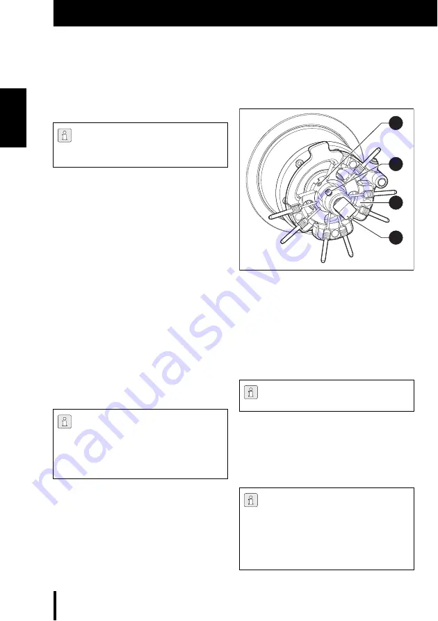
Tool/Blank holder
Fig. 8
Blank holder
1
Screw for holder replacement
2
Screw for blank fastening
3
Blank holder
4
Blank
▷
Insert a blank into the blank holder and tighten
with screw [2].
In addition to standard tools, sister tools can
optionally be inserted in the blank holder. When a
standard tool has reached its wear limit, the mill-
ing machine automatically accesses the respec-
tive sister tool.
To establish the network connection, the
milling machine and the PC must first be
connected via USB.
When operating via a network, up to eight
machines can be connected and controlled
via the CAM software.
The PC and the milling machine must both
be in the same sub-network.
The four standard cutters in tool stations
1 - 4 are mandatory for operation.
The blank holders and tools are colour-
coded depending on application.
▷
Make sure to observe colour assignment
(e.g., orange tools to orange holder). Do
not mix differently colour-coded blank
holders and tools.
2
3
1
4


