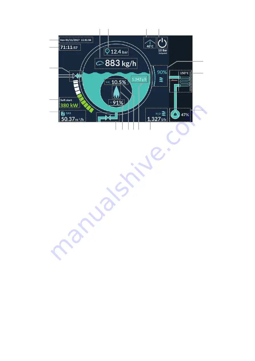
Adjustment and control system
27
Displaying area
1
2
3
4
5
14
13
12
16
18 17
15
11
6
7 8 9 10
1
CURRENT DATE AND TIME
(in display-only mode) to set or edit them, select "user level / general parameters / display-date-time
2
TIME LEFT TO PERIODICAL CHECK (ECS 24 HOURS or ECS72 HOURS)
; The message flashes when there are less than two hours
left to the periodical check. Touch this area to display the messages relating to the checks to be carried out by the SERVICE
(Technical Service). Press
“OK“
to shift to next message and, once finished, the time to next check will be automatically set
(ECS 24 hours or ECS 72 hours)
3
TDS VALVE(Salinity Control Device)
; The valve opening is indicated by an animation. Touch this area to access the configuration
menu of the
TDS
system. When the
TDS
is disabled, below the valve, a red indication appears.
4
ESTIMATED OPERATING POWER
; thermal power estimated on the basis of the burner testing data. SOFT START will be shown
steady on if set in the parameters or flashing if active. Touch this area to access the configuration menu of the burner
5
GAS FLOW RATE
(if the meter is installed)
6
BLOWDOWN VALVE
; the valve opening is indicated by an animation. Touch this area to access the configuration menu of the
valve. When the automatic drain is disabled, below the valve, a red indication appears
7
ESTIMATED COMBUSTION EFFICIENCY
8
FLAME PRESENCE
9
MEASURED CO
2
10
TDS VALUE
(Salinity Control Device). Touch this area to access the configuration menu of the TDS system. When the
TDS
is
disabled, below this value, a red indication appears
11
WATER DELIVERY FLOW RATE
(if the meter is installed)
12
PUMPS OFF / PUMPS 1 and 2 ON with relevant modulation percentage
. Touch this area to access the configuration menu of the
water feed pumps. When a pump is on, the animation indicates the water flow towards the generator
13
FLUE GAS RECOVERY UNIT
; the temperature indicated is detected at the energy saver flue gas outlet
14
WATER LEVEL
; touch this area to access the configuration menu of the water feed pumps
15
GENERATOR START-UP - GENERATOR STATUS
; the icon is white when the safety circuits are open (boiler not ready). To close
them and preset the generator for start-up, press the electromechanical button “I”. The icon is flashing green when the safety
circuits are closed (boiler ready). To open them and stop the generator, press the electromechanical button “0”. The button
turns steady green if it is pressed while flashing, thus operating the burner (steam production start) and, when pressed again,
the burner stops. The setpoint pressure value is indicated under this key
16
AMBIENT TEMPERATURE
(in display-only mode). It indicates the ambient temperature allowing to check that it is within the
design values (+ 5°C m 50 °C maximum)
17
GENERATOR PRESSURE
; touch this area to access the pressure configuration menu
18
STEAM FLOW RATE
(if the meter is installed)
Содержание ECOVAPOR Series
Страница 78: ...Appendixes for Technical Personnel 78...
Страница 79: ...Appendixes for Technical Personnel 79...


