


ICAR PQS
rev8 may18
38 / 86
Set-up: editing page
When the editing screen is displayed, the parameter setting can be modified with ◄ and ►keys. The screen shows the new
setting, a graphic bar that shows the setting range, the maximum and minimum values, the previous setting and the factory default.
Pressing ◄ + ▼the value decreases faster, while with ▲+ ►the value grows faster.
Pressing simultaneously ◄ + ►, the setting is set to factory default. During the entry of a text string, keys ▲and ▼are used to
select the alphanumeric character while◄ and ► are used to move the cursor along the text string. Pressing keys ▲and
▼simultaneously will move the character selection straight to character ‘A’. Press
to go back to the parameter selection. The
entered value is stored.
Press
◄
to save all the settings and to quit the setup menu. The controller executes a reset and returns to normal operation.
If the user does not press any key for more than 2 minutes, the system leaves the setup automatically and goes back to normal
view
ing without saving the changes done on parameters.
N.B.: a backup copy of the setup data (settings that can be modified using the keyboard) can be saved in the eeprom memory of
the power factor controller. This data can be restored when necessary in the work memory. The data backup 'copy' and 'restore'
commands can be found in the commands menu. (
see chapter 27. Command menu
)
20
PARAMETER TABLE
Below are listed all the programming parameters in tabular form. For each parameter are indicated the possible setting range and
factory default, as well as a brief explanation of the function of the parameter. The description of the parameter shown on the
display can in some cases be different from what is reported in the table because of the reduced number of characters available.
The parameter code can be used however as a reference.
Note:
The parameters shown in the table with a shaded background are essential to the operation of the system, thus they
represent the minimum programming required for operation.
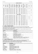
M01 - UTILITY
Psw (M15)
UoM
Default
Range
P01.01
Language
Usr
English
English / Italian / French
Spanish / Portuguese
German / Polish / Czech
Russian / Custom
P01.02
Set clock at system power on
Usr
OFF
OFF-ON
P01.03
LCD contrast
Usr
%
50
0-100
P01.04
Display backlit high intensity
Usr
%
100
0-100
P01.05
Display backlit low intensity
Usr
%
25
0-50
P01.06
Time to switch to low backlighting
Usr
s
180
5-600
P01.07
Return to default page
Usr
s
60
OFF / 10-600
P01.08
Default page
Usr
main
(page list)
P01.09
Plant description
Usr
(empty)
String 20 chr.
P01.01
– Select display text language.
P01.02
– Active automatic clock settings access after power-up.
P01.03
–
Adjust LCD contrast.
P01.04
–
Display backlight high adjustment.
P01.05
–
Display backlight low adjustment.
P01.06
– Display backlight low delay.
P01.07
–
Default page display restore delay when no key pressed. If set to OFF the display will always show the last page selected manually.
P01.08
– Default page displayed on power-up and after delay.
P01.09
– Free text with alphanumeric identifier name of specific panel/plant. If a description is set here, it will be shown as title of the home page. The same
description will be used also for identification after remote reporting alarms/events via SMS/E-mail.
M02 – GENERAL
Psw (M15) UoM
Default
Range
P02.01
CT primary
Usr
A
OFF
OFF/1-30000
P02.02
CT secondary
Usr
A
5
1
5
P02.03
Plant type
Usr
Three-ph
Three-phase
Single phase
P02.04
Current reading phase
Usr
L1
L1
L2
L3
L1 L2 L3
P02.05
CT polarity
Usr
Aut
Aut
Dir
Rev
P02.06
Voltage reading phase
Usr
L1-L2-L3
L1-L2 / L2-L3 / L3-L1
L1-N / L2-N / L3-N / L1-L2-L3
L1-L2-L3-N
Selected parameter
Minimum possible setting
Graph bar of the value-range
New value entered
Maximum possible setting
Factory default setting


