IBM x3850 X5 Скачать руководство пользователя страница 487

Chapter 9. Management 

467

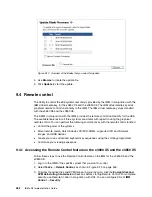
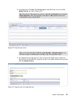
Figure 9-17   Selecting which blade’s video output to display

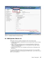
9.5  IBM Systems Director 6.2

IBM Systems Director is a platform manager that offers the following benefits:

򐂰

Enables the management of eX5 physical servers and virtual servers that are running on 
the eX5 platform.

򐂰

Helps to reduce the complexity and costs of managing eX5 platforms. IBM Systems 
Director is the platform management tool for the eX5 platform that provides hardware 
monitoring and management.

򐂰

Provides a central control point for managing your eX5 servers and managing all other 
IBM servers. 

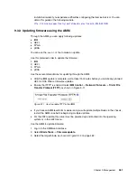
You connect to IBM Systems Director server through a web browser. You can install IBM 
Systems Director server on the following systems: AIX®, Windows, Linux on Power, Linux on 
x86, or Linux on System z®.

Содержание x3850 X5

Страница 1: ...Michael Hurman Jeneea Jervay Eric Kern Cynthia Knight Miroslav Peic Tom Sorcic Evans Tanurdin Covers the IBM System x3950 X5 x3850 X5 x3690 X5 and the IBM BladeCenter HX5 Details technical information...

Страница 2: ......

Страница 3: ...International Technical Support Organization IBM eX5 Implementation Guide May 2011 SG24 7909 00...

Страница 4: ...y GSA ADP Schedule Contract with IBM Corp First Edition May 2011 This edition applies to the following servers IBM System x3850 X5 machine type 7145 IBM System x3950 X5 machine type 7145 IBM System x3...

Страница 5: ...9 1 3 3 IBM BladeCenter HX5 9 1 4 Energy efficiency 10 1 5 Services offerings 11 1 6 What this book contains 11 Part 1 Product overview 13 Chapter 2 IBM eX5 technology 15 2 1 eX5 chip set 16 2 2 Inte...

Страница 6: ...e x3850 M2 61 3 2 Target workloads 63 3 3 Models 64 3 4 System architecture 66 3 4 1 System board 66 3 4 2 QPI Wrap Card 66 3 5 MAX5 68 3 6 Scalability 70 3 6 1 Memory scalability with MAX5 71 3 6 2 T...

Страница 7: ...8 4 Memory balance 139 4 8 5 Mixing DIMMs and the performance effect 140 4 8 6 Memory mirroring 141 4 8 7 Memory sparing 143 4 8 8 Effect on performance of using mirroring or sparing 144 4 9 Storage...

Страница 8: ...ng which SSD RAID configuration to choose 207 5 11 4 Connecting to external SAS storage devices 207 5 12 BladeCenter PCI Express Gen 2 Expansion Blade 208 5 13 I O expansion cards 209 5 13 1 CIOv 209...

Страница 9: ...nd MAX5 configurations 261 6 9 2 UEFI performance tuning 262 6 10 Installing an OS 263 6 10 1 Installing without a local optical drive 263 6 10 2 Use of embedded VMware ESXi 271 6 10 3 Installing the...

Страница 10: ...Server 11 358 7 9 5 VMware vSphere ESXi 4 1 358 7 9 6 VMware vSphere ESX 4 1 362 7 9 7 Downloads and fixes for the x3690 X5 and MAX5 365 7 9 8 SAN storage reference and considerations 367 7 10 Failur...

Страница 11: ...2 3 Updating firmware using the IMM 454 9 3 Advanced Management Module AMM 454 9 3 1 Accessing the Advanced Management Module 456 9 3 2 Service Advisor 458 9 3 3 Updating firmware using the AMM 461 9...

Страница 12: ...for storage management 523 9 14 Serial over LAN 525 9 14 1 Enabling SoL in UEFI 526 9 14 2 BladeCenter requirements 527 9 14 3 Enabling SoL in the operating system 529 9 14 4 How to start a SoL conne...

Страница 13: ...editions of the publication IBM may make improvements and or changes in the product s and or the program s described in this publication at any time without notice Any references in this information t...

Страница 14: ...librated Vectored Cooling DS4000 Dynamic Infrastructure Electronic Service Agent eServer IBM Systems Director Active Energy Manager IBM iDataPlex Netfinity PowerPC POWER Redbooks Redpaper Redbooks log...

Страница 15: ...iness Partners and IBM employees that want to understand the features and capabilities of the IBM eX5 portfolio of servers and want to learn how to install and configure the servers for use in product...

Страница 16: ...IBM STG Lab Services He currently provides technical consulting services for System x BladeCenter System Storage and Systems Software Since 2007 he has helped clients design and implement x86 server a...

Страница 17: ...tions from Microsoft Red Hat and Juniper The authors of this book were divided into two teams Part 1 of the book is based on the IBM Redpaper IBM eX5 Portfolio Overview IBM System x3850 X5 x3950 X5 x3...

Страница 18: ...IBM U S Andrew Spurgeon IBM New Zealand Xiao Jun Wu IBM China Now you can become a published author too Here s an opportunity to spotlight your skills grow your career and become a published author al...

Страница 19: ...n International Technical Support Organization Dept HYTD Mail Station P099 2455 South Road Poughkeepsie NY 12601 5400 Stay connected to IBM Redbooks Find us on Facebook http www facebook com IBMRedboo...

Страница 20: ...xviii IBM eX5 Implementation Guide...

Страница 21: ...These servers scale to more CPU cores memory and I O than previous systems enabling them to handle greater workloads than the systems they supersede Power efficiency and machine density are optimized...

Страница 22: ...w flagship servers of the IBM x86 server family These systems are designed for maximum utilization reliability and performance for computer intensive and memory intensive workloads The IBM System x369...

Страница 23: ...al of 384 GB of memory Backplane connections for four 2 5 inch serial attached SCSI SAS hard disk drives HDDs are standard however the SAS HDDs themselves must be ordered separately A ServeRAID BR10i...

Страница 24: ...er 8x 4GB 4 8 No Yes 2 2 8x 1 8 16c c Includes as standard one 8 bay eXFlash SSD backplane one additional eXFlash backplane is optional Virtualization workload optimized models 7145 4Dx 4x X7550 8C 2...

Страница 25: ...ge on page 145 Model Intel Xeon processors two maximum Memory speed MAX5 Standard memorya a Up to 64 DIMM sockets Each server has 16 DIMM sockets standard or 32 sockets with the addition of the intern...

Страница 26: ...s use the following nomenclature xxU For example the US orderable part number for 7870 A2x is 7870 A2U See the product specific official IBM announcement letter for other country specific GAV model nu...

Страница 27: ...on the processor installed however the memory speed of the MAX5 is up to 1066 MHz irrespective of the processor installed in the attached HX5 MAX5 Scalable to four socket 10GbE cardb b Emulex Virtual...

Страница 28: ...stem image with a max of eight processors and 2 TB of RAM Table 1 9 compares the number of processor sockets cores and memory capacity of the eX4 and eX5 systems Table 1 9 Comparing the x3850 M2 and x...

Страница 29: ...de Center HX5 as shown in Figure 1 4 on page 10 with the second node attached is a blade that exceeds the capabilities of the previous system HS22 The HS22V has more memory in a single wide blade but...

Страница 30: ...g the fan speeds accordingly for optimal cooling efficiency Technologies such as these altimeters along with the Intel Xeon 7500 6500 series processors that intelligently adjust their voltage and freq...

Страница 31: ...Application Enablement Migration Study Virtualization Health Check Rapid Migration Tool IBM Systems Lab Services and Training consists of highly skilled consultants that are dedicated to help you acce...

Страница 32: ...12 IBM eX5 Implementation Guide...

Страница 33: ...servers in the eX5 portfolio This information is most useful in designing configuring and planning to order a server solution This part consists of the following chapters Chapter 2 IBM eX5 technology...

Страница 34: ...14 IBM eX5 Implementation Guide...

Страница 35: ...t memory features MAX5 memory expansion line IBM exclusive system scaling and partitioning capabilities and eXFlash eXFlash can dramatically increase system disk I O by using internal solid state stor...

Страница 36: ...he snoop filter and it is in the shared state must request a copy of the cache line and wait for the result to be returned from the source The eX5 snoop filter contains the contents of the cache lines...

Страница 37: ...ology Intel Hyper Threading Technology enables a single physical processor to execute two separate code streams threads concurrently To the operating system a processor core with Hyper Threading is se...

Страница 38: ...be engaged with any number of cores enabled and active resulting in increased performance of both multi threaded and single threaded workloads Frequency steps are in 133 MHz increments and they depen...

Страница 39: ...f the starting memory locations of the 64 byte chunks of data that are read into cache called cache lines or the actual cache line itself and one of four states modified exclusive shared or invalid ME...

Страница 40: ...emory was accessible through the core chip set by each processor a shared memory architecture This design creates a non uniform memory access NUMA system in which part of the memory is directly connec...

Страница 41: ...hosts reports to a single cluster controller about the resources that remain on the host and the resource demands of any virtual servers running on that host The cluster controller makes decisions to...

Страница 42: ...for a CPU can only be used if a CPU is in that slot If a CPU fails when the system reboots it is brought back online without the failed CPU and without the memory associated with that CPU slot QPI bu...

Страница 43: ...socket in an x3850 X5 Similar configurations apply to the x3690 X5 and HX5 Each configuration has a relative performance score The following key information from this chart is important The best perf...

Страница 44: ...Performance test between ranks With the Xeon 7500 and 6500 processors having more ranks gives better performance The better performance is the result of the addressing scheme The addressing scheme ca...

Страница 45: ...ustry standard STREAM benchmark as shown in Figure 2 7 Figure 2 7 Comparing the performance of memory DIMM configurations using STREAM Taking the top performance result of 16x 4 GB quad rank DIMMs as...

Страница 46: ...n about NUMA installation options see the following sections IBM System x3850 X5 3 8 2 DIMM population sequence on page 79 IBM System x3690 X5 Two processors with memory mezzanine installed on page 13...

Страница 47: ...r and two controllers per processor Each memory channel must contain at least one DIMM to enable Hemisphere Mode Within a processor both memory controllers need to contain identical DIMM configuration...

Страница 48: ...ring you must have both memory cards per processor installed and populate the same amount of memory in both memory cards Partial mirroring mirroring of part but not all of the installed memory is not...

Страница 49: ...sections IBM System x3850 X5 3 8 5 Memory sparing on page 89 IBM System x3690 X5 4 8 7 Memory sparing on page 143 IBM BladeCenter HX5 5 10 5 Memory sparing on page 202 Chipkill Chipkill memory technol...

Страница 50: ...mple if a memory location in a DIMM no longer functions properly and it cannot be recovered by the DIMM or memory controller logic MCA logs the failure and prevents that memory location from being use...

Страница 51: ...r eX5 MAX5 is the name give to the memory and scalability subsystem that can be added to eX5 servers In the Intel QPI specification the MAX5 is a node controller MAX5 for the rack mounted systems x385...

Страница 52: ...5 is the 1U unit beneath the main system Figure 2 11 shows the MAX5 removed from the housing Figure 2 11 IBM MAX5 for the x3850 X5 and x3690 X5 MAX5 connects to these systems through QPI links and pro...

Страница 53: ...rchitecture also supports memory scaling Figure 2 12 shows these types of scaling Figure 2 12 Types of scaling with eX5 systems The x3850 X5 and HX5 both support 2 node system scaling or memory scalin...

Страница 54: ...eCenter HX5 5 8 Scalability on page 188 2 6 Partitioning You can operate the HX5 scaled system as two independent systems or as a single system without removing the blade and taking off the side scale...

Страница 55: ...em types with little additional work and it allows you more flexibility in system types for better workload optimization The HX5 blade when scaled as a 2 node 4 socket system supports FlexNode partiti...

Страница 56: ...eal mode limitation that BIOS had Obtain more information about UEFI at the following website http www uefi org home Many of the advanced technology options that are available in the eX5 systems are c...

Страница 57: ...Chapter 2 IBM eX5 technology 37 Figure 2 17 UEFI settings main panel Choose System Settings to access the system settings options that we will describe here as shown in Figure 2 18 on page 38...

Страница 58: ...the server In most operating conditions the default settings are ideal to provide the best performance possible without wasting energy during off peak usage However for certain workloads it might be a...

Страница 59: ...rs by setting the processors QPI link and memory subsystem to a lower working frequency Acoustic Mode provides lower system acoustics less heat and the lowest power consumption at the expense of perfo...

Страница 60: ...tem performance at the expense of power efficiency Figure 2 22 Performance Mode predetermined values Performance Mode is also a good choice when the server runs virtualization workloads Servers that a...

Страница 61: ...e recommended factory default setting The values are set to provide optimal performance with reasonable power consumption However this mode allows the user to individually set the power related and pe...

Страница 62: ...energy management of IBM servers storage and networking equipment In addition Active Energy Manager extends the scope of energy management to include non IBM systems facility providers facility manage...

Страница 63: ...However individual system settings enable users to fine tune the desired characteristics of the IBM eX5 servers This section describes the UEFI settings that are related to system performance Remember...

Страница 64: ...in relation to power consumption Turbo Mode does not engage unless additional performance has been requested by the operating system for a period of 2 seconds Traditional provides a more aggressive Tu...

Страница 65: ...stored in the processor cache Cores in CPU Package Default All This option sets the number of processor cores to be activated QPI Link Frequency Default Max Performance This option sets the operating...

Страница 66: ...ess performance for better power savings The memory operates at the lowest supported frequency which in the eX5 systems is 800 MHz Power Efficiency provides the best performance per watt ratio The mem...

Страница 67: ...AS Widget The widget allows multiple consecutive column address strobes CAS to the same memory ranks and banks in the Open Page Policy Mapper Policy Default Closed This option determines how memory pa...

Страница 68: ...write operations such as transaction processing media streaming surveillance file copy logging backup and recovery and business intelligence In addition to its superior performance eXFlash offers supe...

Страница 69: ...the number of variables involved However in most circumstances we expect the scale of the performance differential between these two product types to remain constant If we take a 146 GB 15K RPM 2 5 i...

Страница 70: ...ent tools such Virtual Center Remote Command Line Interface CLI and Common Information Model CIM for standards based and agentless hardware monitoring VMware ESXi includes full VMware File System VMFS...

Страница 71: ...mory when using an UEFI aware 64 bit operating system the question that comes to mind with a non virtualized operating system is Do I continue to use a swap file to increase the amount of usable memor...

Страница 72: ...ing demand to additional virtual servers as demand increases As the peak demand subsides the same environment can automatically consolidate virtual servers to a smaller group of active hosts saving po...

Страница 73: ...ent server to off load the processing time that is needed to maintain those client sessions You can define the same physical servers as virtual servers with access to a collection of SSD drives The nu...

Страница 74: ...54 IBM eX5 Implementation Guide...

Страница 75: ...n additional 32 DIMM sockets It is ideal for applications that can take advantage of as much memory as is available This chapter contains the following topics 3 1 Product features on page 56 3 2 Targe...

Страница 76: ...1 1 IBM System x3850 X5 product features IBM System x3850 X5 machine type 7145 is the follow on product to the IBM System x3850 M2 and x3950 M2 It is a 4U 4 socket Intel 7500 based Nehalem EX platfor...

Страница 77: ...I SAS backplanes have been installed at the right of the server Each backplane supports four 2 5 inch SAS disks eight disks in total Notice the orange colored bar on each disk drive This bar denotes t...

Страница 78: ...lable PCIe 2 0 slots Two 60mm hot swap fans Eight SAS 2 5 drives or two eXFlash SSD units Two 120mm hot swap fans Two front USB ports Light path diagnostics DVD drive Dual port 10Gb Ethernet Adapter P...

Страница 79: ...isphere Mode see 2 3 5 Hemisphere Mode on page 26 The IBM x3950 X5 is optimized for database workloads and virtualization workloads Virtualization optimized models of the x3950 X5 include a MAX5 as st...

Страница 80: ...t in fans for redundancy support 675 watt 110 220 V ac auto sensing One power supply standard two maximum second power supply is for redundancy Light path diagnostics LEDs Board LED Configuration LED...

Страница 81: ...4 Comparing the x3850 X5 to the x3850 M2 Table 3 1 on page 62 shows a high level comparison between the eX4 based x3850 M2 and the eX5 based x3850 X5 Power on LED Locate LED System error LED AC LED gr...

Страница 82: ...D 1 Upgrade key for RAID 5 SAS 4x external port for EXP3000 attach Ethernet controller BCM 5709 dual port Gigabit Ethernet PCIe 2 0 x4 Dual port Emulex 10Gb Ethernet adapter in PCIe slot 7 on all mode...

Страница 83: ...e Enhanced VMotion Database Database workloads require powerful CPUs and disk subsystems that are configured to deliver high I O per second IOPS from sheer memory capacity although the importance of s...

Страница 84: ...space for an additional eight SSDs You must order the SSDs separately Because no SAS controllers are standard you can select from the available cards that are described in 3 9 Storage on page 90 Model...

Страница 85: ...kload optimized models 7145 5Dx X7560 8C 2 27 GHz 24 MB L3 130W 1066 MHz Opt Server 8x 4GB 4 8 No Yes 2 2 None Virtualization workload optimized models 7145 4Dx 4x X7550 8C 2 0 GHz 18 MB L3 130W 1066...

Страница 86: ...rd In the x3850 X5 QPI links are used for interprocessor communication both in a single node system and in a 2 node system They are also used to connect the system to a MAX5 memory expansion drawer In...

Страница 87: ...t by ensuring that all CPUs are only one hop away from each other as shown in Figure 3 9 Figure 3 9 Location of QPI Wrap Cards Tip The QPI Wrap Cards are only for single node configurations with three...

Страница 88: ...attach a MAX5 expansion unit or connect a second node you must first remove the QPI Wrap Cards Figure 3 10 Rear of the x3850 X5 3 5 MAX5 As introduced in 3 1 3 IBM MAX5 memory expansion unit on page...

Страница 89: ...X5 not only has that same data stored in its own cache it is able to return the acknowledgement of the snoop and the data to the requesting CPU in the same transaction For more information about QPI l...

Страница 90: ...umber of processors and the number of memory DIMMs The x3850 X5 currently supports the following scalable configurations A single x3850 X5 server with four processor sockets This configuration is some...

Страница 91: ...QPI cables See Table 3 7 Table 3 7 Ordering information for the IBM MAX5 to x3850 X5 Cable Kit 3 6 2 Two node scalability The 2 node configuration also uses native Intel QPI scaling to create an 8 so...

Страница 92: ...hich are located a few inches inside on the planar Completing the QPI scaling of two x3850 X5 servers into a 2 node complex does not require any other option Figure 3 15 on page 73 shows the QPI links...

Страница 93: ...stem until the cables are physically disconnected Firmware levels It is important to ensure that both of the x3850 X5 servers have the identical UEFI integrated management module IMM and Field Program...

Страница 94: ...ty of bending pins on the processor socket when using the incorrect procedure The x3850 X5 includes at least two CPUs as standard Two CPUs are required to access all seven of the PCIe slots shown in F...

Страница 95: ...part number 49Y4379 to improve performance The kit contains two wrap cards See 3 4 2 QPI Wrap Card on page 66 When using a MAX5 memory expansion unit as shown in Figure 3 12 on page 70 you maximize pe...

Страница 96: ...nce on page 79 3 8 3 Maximizing memory performance on page 84 3 8 4 Memory mirroring on page 87 3 8 5 Memory sparing on page 89 3 8 6 Effect on performance by using mirroring or sparing on page 89 3 8...

Страница 97: ...X5 memory card The memory cards are installed in the server as shown in Figure 3 17 Each processor is electrically connected to two memory cards as shown for example processor 1 is connected to memory...

Страница 98: ...mory bus speed and the DIMM memory bus speed Ranks 44T1592 1712 2 GB 1x 2GB 1Rx8 2 Gb PC3 10600R DDR3 1333 Yes fc 2429 1333 MHzb b Although 1333 MHz memory DIMMs are supported in the x3850 X5 the memo...

Страница 99: ...2GB 1Rx8 2Gbit PC3 10600R DDR3 1333 Yes 1333 MHzb b Although 1333 MHz memory DIMMs are supported in the x3690 X5 the memory DIMMs run at a maximum speed of 1066 MHz Single x8 44T1599 2431 4 GB 1x 4GB...

Страница 100: ...t only memory configurations that are considered the best practices in obtaining the optimal memory and processor performance For a full list of supported memory configurations see the IBM System x385...

Страница 101: ...x x x x x x x x x x x x x x 42 N x x x x x x x x x x x x x x x x x x x x x 48 Y x x x x x x x x x x x x x x x x x x x x x x x x Three processor system For a 3 processor system you can use either proc...

Страница 102: ...gure 3 18 on page 83 shows the numbering scheme for the DIMM slots on the MAX5 and the pairing of DIMMs in the MAX5 As DIMMs are added in pairs they must be matched on a memory port as shown by using...

Страница 103: ...ory buffer 6 4 3 2 1 0 1 Memory buffer 4 0 1 0 1 Memory buffer 1 DIMM 29 DIMM 30 DIMM 31 DIMM 32 32 31 30 29 DIMM 28 DIMM 27 DIMM 26 DIMM 25 28 27 26 25 Memory buffer 2 0 1 0 1 Memory buffer 8 DIMM 21...

Страница 104: ...Maximizing memory performance In a single node x3850 X5 that is populated with four CPUs and eight memory cards there are a total of 16 memory buffers as shown in the system block diagram in Figure 3...

Страница 105: ...rd requires at least two DIMMs Each processor and memory card must have identical amounts of RAM Install and populate two memory cards per processor or you can lose memory bandwidth 1 Each processor 2...

Страница 106: ...atform s DIMMs Certain configurations might attempt to use the DIMMs that came with the base platform along with optional DIMMs of a separate type Figure 3 20 on page 87 illustrates the relative perfo...

Страница 107: ...ctable by the user For a detailed understanding of memory mirroring see Memory mirroring on page 28 x3850 X5 memory mirroring population order Table 3 17 on page 88 shows DIMM placements for each solu...

Страница 108: ...IMM 1 and 8 DIMM 3 and 6 DIMM 2 and 7 DIMM 4 and 5 DIMM 1 and 8 DIMM 3 and 6 DIMM 2 and 7 DIMM 4 and 5 DIMM 1 and 8 DIMM 3 and 6 DIMM 2 and 7 DIMM 4 and 5 4 x x 8 x x x x 12 x x x x x x 16 x x x x x x...

Страница 109: ...em Rank sparing is applied on all memory cards in the system These options are configured by using the UEFI during boot 3 8 6 Effect on performance by using mirroring or sparing To understand the effe...

Страница 110: ...SD support on page 93 3 9 4 SAS and SSD controllers on page 96 3 9 6 External storage connectivity on page 101 3 9 1 Internal disks The x3850 X5 supports one of the following sets of drives in the int...

Страница 111: ...le included with the part number 59Y6135 and it is always controlled by the RAID adapter in the dedicated slot behind the disk cage never from an adapter in the PCIe slots The required power signal Y...

Страница 112: ...O CTIO for SSD FastPath optimization on ServeRAID M5014 M5015 and M5025 controllers a The battery is not included with the ServeRAID M5015 Part number Feature code Description 42D0632 5537 IBM 146 GB...

Страница 113: ...e eight drive bays require the same physical space as four SAS hard disk bays A single eXFlash backplane requires two SAS x4 input cables and a power configuration cable which are both shipped standar...

Страница 114: ...st Bus Adapter No RAID support 46M0831 0095 ServeRAID M1015 SAS SATA Controller 46M0829 0093 ServeRAID M5015 SAS SATA Controllera a When using SSD drives you must disable the write back cache to preve...

Страница 115: ...AS SATA Controller performance to match an array of SSDs Flash tiering enablement A data tiering enabler to support hybrid environments of SSDs and HDDs realizing higher levels of performance MegaRAID...

Страница 116: ...087 connectors SAS 3 Gbps PCIe x8 host bus interface Fixed 64 KB stripe size Part number Feature code Name Supports 2 5 inch SAS backplane Supports eXFlash SSD backplane Dedicated slot a a See 3 9 5 D...

Страница 117: ...SATA in the same RAID array is not supported Up to 64 logical volumes Logical unit number LUN sizes up to 64 TB Configurable stripe size up to 1 MB Compliance with Disk Data Format DDF configuration o...

Страница 118: ...ions Up to 240 SAS or SATA drives Up to nine daisy chained enclosures per port SAS and SATA drives are supported but mixing SAS and SATA drives in the same RAID array is not supported Support for up t...

Страница 119: ...and self encrypting drives SED technology are optional upgrades to the ServeRAID M1015 adapter with the addition of the ServeRAID M1000 Series Advanced Feature Key part number 46M0832 feature code 974...

Страница 120: ...n see ServeRAID B5015 SSD Controller TIPS0763 which is available at the following website http www redbooks ibm com abstracts tips0763 html Open 3 9 5 Dedicated controller slot As listed in Table 3 27...

Страница 121: ...FF 8088 Six Gbps throughput per SAS port 800 MHz PowerPC processor with LSI SAS2108 6 Gbps RAID on Chip ROC controller PCI Express 2 0 x8 host interface 512 MB onboard data cache DDR2 running at 800 M...

Страница 122: ...th SAS and SSD with the optional M5000 Series Performance Accelerator Key which enables the following features RAID levels 6 and 60 Performance optimizations for SSDs LSI SafeStore Support for SED ser...

Страница 123: ...ut the slots Slot 1 can accommodate a double wide x16 card but access to slot 2 is then blocked Slot 2 is described as x4 x8 mechanical This host interface is sometimes shown as x4 x8 and means that t...

Страница 124: ...endor s logo is displayed click it to assess options that the vendor has qualified on the x3850 X5 You can obtain the support caveats for third party options in 3 12 2 Optional adapters on page 107 In...

Страница 125: ...re 3 27 Figure 3 27 The Emulex 10Gb Ethernet Adapter has a blue circuit board and a longer connector The Emulex 10Gb Ethernet Adapter is a customer replaceable unit CRU To replace the adapter for exam...

Страница 126: ...ram protocol UDP checksum off load Virtual LAN VLAN insertion and extraction Support for jumbo frames up to 9000 bytes Preboot eXecutive Environment PXE 2 0 network boot support Interrupt coalescing L...

Страница 127: ...al Transceiver 46C3447 5053 BNT SFP Transceiver Option Feature code Description Networking 59Y1887 5763 QLogic QLE7340 single port 4X QDR IB x8 PCI E 2 0 HCA 39Y6071 1485 NetXtreme II 1000 Express G E...

Страница 128: ...n in ServerProven use ServerProven as the definitive resource The main function of ServerProven is to show the options that have been successfully tested by IBM with a System x server Another useful p...

Страница 129: ...or half duplex mode Two direct memory access DMA engines maximize the bus throughput and minimize CPU overhead The onboard Ethernet offers these features TCP off load engine TOE acceleration Shared P...

Страница 130: ...s System temperatures Fan speed control Fan tachometer monitor Good Power signal monitor System ID and planar version detection System power and reset control Non maskable interrupt NMI detection syst...

Страница 131: ...ting system volume and provide integrity authentication for a trusted boot pathway such as BIOS boot sector and others A number of vendor full disk encryption products also support the TPM chip The x3...

Страница 132: ...power supplies One or two dual rated power supplies are standard model dependent see 3 3 Models on page 64 1975 watts at 220 V ac input 875 watts at 110 V ac input Hot swappable and redundant at 220...

Страница 133: ...m x3850 X5 of a 2 node complex when QPI cables directly link the two servers 3 14 2 MAX5 power supplies and fans The MAX5 power subsystem consists of one or two hot pluggable 675W power supplies The p...

Страница 134: ...Server 2008 R2 Datacenter x64 Edition Microsoft Windows Server 2008 R2 Enterprise x64 Edition Microsoft Windows Server 2008 R2 Standard x64 Edition Microsoft Windows Server 2008 R2 Web x64 Edition Win...

Страница 135: ...designed for 26 inch deep devices such as the NetBAY42 ER NetBAY42 SR NetBAY25 SR or NetBAY11 The 5U combination of MAX5 and x3850 X5 is mechanically joined and functions as a single unit Adding the...

Страница 136: ...116 IBM eX5 Implementation Guide...

Страница 137: ...cture servers The server delivers innovation with enhanced reliability and availability features to enable optimal performance for databases enterprise applications and virtualized environments This c...

Страница 138: ...emory sparing Intel scalable memory interconnect SMI Lane Failover SMI Packet Retry and SMI Clock Failover Serial Attached SCSI SAS based internal storage with RAID 0 RAID 1 or RAID 10 to maximize thr...

Страница 139: ...nd blue for non hot swappable The only hot swappable parts in this server are the HDDs fans and power supplies All other parts require that the server is powered off before removing that component 4 1...

Страница 140: ...management Ethernet connector Video Serial connector USBs 3 4 USBs 5 6 Ethernet 1 Ethernet 2 Power supply 1 Power supply 2 Power supply 4 QPI port 1 QPI port 2 Two CPU sockets partially covered by th...

Страница 141: ...Figure 4 5 shows the x3690 X5 with the attached MAX5 Figure 4 5 x3690 X5 with the attached MAX5 memory expansion unit The MAX5 has the following specifications IBM EXA5 chip set Intel memory controlle...

Страница 142: ...total of 64 DIMM sockets Using 16 GB DIMMs you can install a total of 1 TB of RAM All DIMM sockets in the MAX5 are accessible regardless of whether one or two processors are installed in the x3690 X5...

Страница 143: ...uting in a dense package Target workloads include the following items Virtualization consolidation or virtual desktop The x3690 X5 with only two sockets can support as many virtual machines as older 4...

Страница 144: ...maximum Memory speed MAX5 Standard memorya a Up to 64 DIMM sockets Each server has 16 DIMM sockets standard or 32 sockets with the addition of the internal memory tray mezzanine With the addition of t...

Страница 145: ...s space for an additional twelve 2 5 inch disk drives You must order the actual drives separately See 4 9 Storage on page 145 for details Table 4 2 x3690 X5 workload optimized models Model Intel Xeon...

Страница 146: ...100 Management port Serial port 6x USB SATA DVD Video ports FPGA x16 PCIe Slot 1 Intel I O Hub x8 PCIe LP Slot 3 x8 PCIe LP Slot 5 x4 PCIe LP Slot 4 Dual Port Gb Ethernet Intel Southbridge Slot 5 key...

Страница 147: ...adds additional memory performance The eX5 chip connects directly through QPI links to both CPUs in the x3690 X5 and it maintains a directory of each CPU s last level cache This directory allows the...

Страница 148: ...er Therefore when a CPU requests content stored in the cache of another CPU the MAX5 not only has that same data stored in its own cache it is able to return the acknowledgement of the snoop and the d...

Страница 149: ...node x3690 X5 requires one IBM MAX5 to x3690 X5 Cable Kit which consists of two QPI cables See Table 4 4 Table 4 4 Ordering information for the IBM MAX5 to x3690 X5 Cable Kit Two node configurations...

Страница 150: ...Threading Technology TBc c Intel Turbo Boost Technology MAX5 Advanced processors X 60Y0311 4469 Xeon X7560 8C 2 26 GHz 24 MB 6 4 GT s 1066 MHz 130W Yes Yes Yes 60Y0313 4471 Xeon X7550 8C 2 00 GHz 18...

Страница 151: ...ndation is to have two processors installed and memory installed in every DIMM socket in the server to maximize performance If high processing capacity is not required for your application but high me...

Страница 152: ...sor 1 connects directly to the memory buffers and memory in the memory mezzanine If you plan to install the memory mezzanine you are required to also install the second processor The x3690 X5 uses the...

Страница 153: ...Rx8 2Gbit PC3 10600R DDR3 1333 Yes fc 2431 1333 MHz Dual x8 46C7448 1701 4 GB 1x 4GB 4Rx8 1Gbit PC3 8500 DDR3 1066 No 1066 MHz Quad x8 46C7482 1706 8 GB 1x 8GB 4Rx8 2Gbit PC3 8500 DDR3 1066 Yes fc 243...

Страница 154: ...main memory through processor 1 resulting in a performance degradation to processor 2 When the memory mezzanine is not installed install the DIMMs in the order that is listed in Table 4 8 on page 135...

Страница 155: ...x x x x x 1 or 2 8 Y x x x x x x x x 1 or 2 10 N x x x x x x x x x x 1 or 2 12 Y x x x x x x x x x x x x 1 or 2 14 N x x x x x x x x x x x x x x 1 or 2 16 Y x x x x x x x x x x x x x x x x Important...

Страница 156: ...MM 15 DIMM 16 DIMM 17 DIMM 18 DIMM 19 DIMM 20 DIMM 21 DIMM 22 DIMM 23 DIMM 24 DIMM 25 DIMM 26 DIMM 27 DIMM 28 DIMM 29 DIMM 30 DIMM 31 DIMM 32 4 N x x x x 8 Y x x x x x x x x 12 N x x x x x x x x x x x...

Страница 157: ...processor memory bus speed and the DIMM memory bus speed Ranks 44T1592 2429 2 GB 1x 2GB 1Rx8 2Gbit PC3 10600R DDR3 1333 Yes 1333 MHzb b Although 1333 MHz memory DIMMs are supported in the x3690 X5 the...

Страница 158: ...re 4 16 DIMM numbering on MAX5 Table 4 11 shows the population order of the MAX5 DIMM slots which ensures that memory is balanced among the memory buffers The colors in Table 4 11 match the colors in...

Страница 159: ...t setting in Unified Extensible Firmware Interface UEFI See 7 8 UEFI settings on page 337 for details 4 8 4 Memory balance The Xeon 7500 Series processor uses a nonuniform memory access NUMA architect...

Страница 160: ...ed memory configuration While these configurations use 4 GB 4R x8 and 2 GB 2R x8 DIMMs as specified similar trends to this data are expected when using other mixed DIMM capacities In all cases memory...

Страница 161: ...pported For a detailed understanding of memory mirroring see Memory mirroring on page 28 DIMM installation for 3690 X5 Table 4 12 lists the DIMM installation sequence for memory mirroring mode when on...

Страница 162: ...DIMM 16 DIMM 17 DIMM 18 DIMM 19 DIMM 20 DIMM 21 DIMM 22 DIMM 23 DIMM 24 DIMM 25 DIMM 26 DIMM 27 DIMM 28 DIMM 29 DIMM 30 DIMM 31 DIMM 32 4 x x x x 8 x x x x x x x x 12 x x x x x x x x x x x x 16 x x x...

Страница 163: ...configured as spares The ranks have to be as large as the rank relative to the highest capacity DIMM that we are sparing The size of the two unused ranks for sparing is subtracted from the usable cap...

Страница 164: ...th sixty four 4 GB quad rank DIMMs Figure 4 19 shows the peak system level memory throughput for various memory modes measured using an IBM internal memory load generation tool As shown there is a 50...

Страница 165: ...ven compat us 4 9 1 2 5 inch SAS drive support The server supports up to sixteen 2 5 inch disk drives These drives are connected to the server using hot swap backplanes either four drive backplanes or...

Страница 166: ...plane part numbers Part number Feature code Backplane Drives supported SAS cables includeda a See the next paragraph for a description of short and long cables The option part numbers include the cabl...

Страница 167: ...gnal connector SAS power connector 4x 2 5 inch drive backplane one SAS connection 8x 2 5 inch drive backplane two SAS connections Part number Feature code Description Backplane used 42D0672 5522 IBM 7...

Страница 168: ...SATA drive with mounting hardware You can use the single SATA drive as a boot drive when the system is populated with eXFlash SSDs The single SATA HDD bay Table 4 21 is installed in the rightmost HDD...

Страница 169: ...as Compatibility As listed in Table 4 19 on page 147 the 2 5 inch 50 GB SSD is also supported with the standard SAS backplane and the option SAS backplane part numbers 60Y0338 and 60Y0369 It is not co...

Страница 170: ...ve backplanes Figure 4 23 shows the 8x 1 8 inch SSD backplane with its two SAS connectors Figure 4 23 8x 1 8 inch SSD backplane rear view Table 4 24 lists the supported 1 8 inch SSDs Table 4 24 x3690...

Страница 171: ...Description 46M0914 3876 IBM 6Gb SSD Host Bus Adapter No RAID support 46M0829 0093 ServeRAID M5015 SAS SATA Controllera a Add the Performance Accelerator Key to the ServeRAID M5015 or M5014 for use w...

Страница 172: ...mary In this section we provide details for the features of each controller card and what they offer Table 4 26 lists the SAS controllers that are supported in the x3690 X5 Most models of the x3690 X5...

Страница 173: ...5 10 and 50 RAID 6 and 60 support with the optional M5000 Advanced Feature Key Connection of up to 32 SAS or SATA drives SAS and SATA drives are supported but mixing SAS and SATA in the same RAID arr...

Страница 174: ...D volume SSD support Two mini SAS internal connectors SFF 8087 Throughput of 6 Gbps per port LSI SAS2008 6 Gbps RAID on Chip ROC controller x8 PCI Express 2 0 host interface RAID levels 0 1 and 10 sup...

Страница 175: ...ress 2 0 x8 host interface PCI MD2 low profile form factor Two x4 internal SFF 8087 connectors SAS controller PMC Sierra PM8013 maxSAS 6 Gbps SAS RoC controller Up to eight disk drives per RAID adapte...

Страница 176: ...interposer Plastic stand off Two screws The screws and stand off attach the interposer to the RAID controller after the battery is removed Figure 4 25 shows these components Figure 4 25 Remote battery...

Страница 177: ...input connectors which you connect to a supported RAID controller plus four output connectors to go to each backplane which allows you to connect to up to 16 drives Figure 4 27 ServeRAID Expansion Ada...

Страница 178: ...wo 4x HDD backplanes in use This configuration requires two SAS cables Figure 4 29 x3690 with two IBM 4x 2 5 inch HS SAS HDD backplanes Figure 4 30 on page 159 shows a configuration that uses one 8x H...

Страница 179: ...SSD backplane Configurations with 12 drives Figure 4 32 shows three 4x HDD backplanes This configuration requires three SAS cables Figure 4 32 x3690 with three IBM 4x 2 5 inch HS SAS HDD backplanes F...

Страница 180: ...690 with two IBM 8x 2 5 inch HS SAS HDD backplanes Figure 4 37 illustrates another 16 drive configuration with one 8x and two 4x backplanes Also you can configure this system with the two 4x backplane...

Страница 181: ...e SATA drive Configurations with 20 drives Figure 4 40 shows a full complement of drives using three 4x backplanes and one 8x eXFlash backplane Also you can achieve this configuration with one 8x back...

Страница 182: ...rs two external SAS ports to connect to external storage Table 4 29 lists the cards support cables and feature keys Table 4 29 External ServeRAID card The M5025 has two external SAS 2 0 x4 connectors...

Страница 183: ...ced Feature Key which enables the following features RAID levels 6 and 60 LSI SafeStore Support for self encrypting drive services such as instant secure erase and local key management which requires...

Страница 184: ...f which are installed as standard Figure 4 45 on page 164 shows the locations of the two riser cards in the server Figure 4 45 Location of the PCIe riser cards in the server DVD ROM The DVD ROM drive...

Страница 185: ...x4 low profile adapter x8 mechanical Slot 5 PCIe 2 0 x8 low profile adapter The Emulex 10Gb Ethernet adapter is installed in this slot if the adapter is part of the server configuration Table 4 32 lis...

Страница 186: ...custom built Emulex 10Gb Ethernet Adapter that is shown in Figure 4 46 on page 166 Figure 4 46 The Emulex 10Gb Ethernet Adapter has a blue circuit board and a longer connector The Emulex 10Gb Ethernet...

Страница 187: ...n Support for jumbo frames up to 9000 bytes Preboot eXecutive Environment PXE 2 0 network boot support Interrupt coalescing Load balancing and failover support Deployment and management of this adapte...

Страница 188: ...340 single port 4X QDR IB x8 PCI E 2 0 HCA 39Y6071 1485 NetXtreme II 1000 Express G Ethernet Adapter PCIe 49Y4253 5749 Emulex 10GbE Virtual Fabric Adapter 49Y4243 5768 Intel Ethernet Quad Port Server...

Страница 189: ...I2 C and general purpose I Os Matrox G200 Video core DDR2 250 MHz memory controller USB 2 0 configurable peripheral Avocent digital video compression The IMM has the following system management featur...

Страница 190: ...the server as shown in Figure 4 2 on page 119 and four on the rear of the server as shown in Figure 4 3 on page 120 rear The server also has two internal USB ports located on riser card 2 as shown in...

Страница 191: ...pply internal fans that are located at the rear of each power supply Fans are numbered left to right if you are looking at the front of the chassis Fan 1 is nearest the power supplies and Fan 5 is nea...

Страница 192: ...8 x3690 X5 fans Figure 4 49 shows the top of the server and the hot swap fan access panel Figure 4 49 Hot swap fan access panel The following conditions affect system fan speed adjustments Inlet Ambie...

Страница 193: ...th power supplies use the IBM 675W Redundant Power Supply Kit part number 60Y0327 The power subsystem is designed for N N operation and hot swap exchange Having four power supplies installed allows fo...

Страница 194: ...based on altitude and ambient temperature Fans also respond to certain conditions and come up to speed accordingly If a fan fails the remaining fans spin up to full speed As the internal temperature...

Страница 195: ...90 X5 support for operating systems includes the following items Microsoft Windows Server 2008 Datacenter x64 Edition Microsoft Windows Server 2008 Enterprise x64 Edition Microsoft Windows Server 2008...

Страница 196: ...he ServerProven Plan for x3690 X5 for details and the full list of supported operating systems at the following website http ibm com systems info x86servers serverproven compat us nos matrix shtml VMw...

Страница 197: ...age 181 5 3 Chassis support on page 182 5 4 Models on page 183 5 5 System architecture on page 184 5 6 Speed Burst Card on page 185 5 7 IBM MAX5 for BladeCenter on page 186 5 8 Scalability on page 188...

Страница 198: ...eries processors and 40 DIMM sockets 16 in the HX5 server and 24 in the attached MAX5 memory expansion blade Figure 5 1 IBM BladeCenter HX5 blade server configurations Table 5 1 lists the features of...

Страница 199: ...Low Profile VLP Registered DIMMs DIMMs per channel 1 1 HX5 1 MAX5 2 Internal storage Optional 1 8 inch solid state drives SSDs Non hot swap require an additional SSD carrier Maximumnumberof drives Tw...

Страница 200: ...HS22V HX5 HX5 with MAX5 Form factor 30 mm blade 1 wide 30 mm blade 1 wide 30 mm blade 1 wide 60 mm blade 2 wide 60 mm blade 2 wide Processor Intel Xeon Processor 5500 and 5600 Intel Xeon Processor 55...

Страница 201: ...One MAX5 Two DIMM sockets 12 18 30 mm 16 60 mm 32 40 Maximum installable RAM 8 GB DIMMs 96 GB 144 GB 30 mm 128 GB 60 mm 256 GB 320 GB Memory type DDR3 ECC VLP RDIMMs DDR3 ECC and non ECC VLP RDIMMs DD...

Страница 202: ...HX5 chassis compatibility Description BC E 8677 BC S 8886 BC H 8852 BC HT ac 8750 BC HT dc 8740 HX5 server No Yes Yesa a One node and 2 node HX5 configurations with 130W processors are not supported...

Страница 203: ...5 Scale to four socket 10 GbE cardb b Emulex Virtual Fabric Adapter Expansion Card CFFh Standard memoryc c The HX5 has 16 DIMM sockets and can hold 128 GB using 8 GB memory DIMMs The MAX5 has 24 DIMM...

Страница 204: ...rs each with two memory channels One DIMM per memory channel 16 DDR3 DIMM sockets One Broadcom BCM5709S dual port Gigabit Ethernet controller One Integrated Management Module IMM One Trusted Platform...

Страница 205: ...he system SMI links QPI links QPI QPI ESI x4 PCIe x1 x16 x4 USB Hypervisor CIOv I O connector 16 DDR3 memory DIMMs one DIMM per channel Memory buffer Memory buffer Memory buffer Memory buffer Scalabil...

Страница 206: ...n blade that attaches to HX5 2 socket blade servers It has the following system architecture features IBM EXA memory controller Twenty four DIMM slots and 6 memory buffers Four DIMM slots per memory b...

Страница 207: ...power domains A B and C Each power domain includes two memory controllers and eight DIMM sockets Figure 5 7 shows the layout of the MAX5 Figure 5 7 MAX5 memory expansion blade In the next section 5 8...

Страница 208: ...st the supported BladeCenter chassis for each configuration in 5 3 Chassis support on page 182 5 8 1 Single HX5 configuration This server is the base configuration and supports one or two processors t...

Страница 209: ...hed The scaling is performed through QPI scaling The 2 node scalability card is not included with the server and must be ordered separately as listed in Table 5 9 Table 5 9 HX5 2 Node Scalability Kit...

Страница 210: ...e and deleting the partition see 8 6 Creating an HX5 scalable complex on page 402 5 8 3 HX5 with MAX5 In the HX5 and MAX5 configuration the HX5 and MAX5 units connect through a 1 node MAX5 scalability...

Страница 211: ...ion Table 5 10 HX5 1 Node Scalability Kit Figure 5 11 shows the block diagram of the single node HX5 with MAX5 Figure 5 11 HX5 1 node with MAX5 block diagram Part number Feature code Description 59Y58...

Страница 212: ...a The first feature code is for the first processor The second feature code is for the second processor Description Supported model 46M6955 4571 4572 Intel Xeon E6540 Processor 2 00 GHz 6C 105W 18M 6...

Страница 213: ...e memory speeds If a MAX5 memory expansion blade is installed the memory in the MAX5 can operate as high as 1066 MHz depending on the DIMMs installed The MAX5 memory speed is independent of the HX5 me...

Страница 214: ...s Table 5 13 lists the memory options for the HX5 and MAX5 They are the same options for both products with the exception of the 2 GB DIMM option Table 5 13 Memory options HX5 and MAX5 Tip Memory must...

Страница 215: ...ust be connected to an HX5 system only the 1 node HX5 supports the MAX5 has one memory controller and six SMI connected memory buffers DDR 3 DIMM 13 DDR 3 DIMM 14 DDR 3 DIMM 15 DDR 3 DIMM 16 DDR 3 DIM...

Страница 216: ...er Installing DIMMs in the HX5 and MAX5 in the correct order is essential for system performance See 5 10 4 Memory mirroring on page 200 for the effects on performance when you do not install the DIMM...

Страница 217: ...ory subsystem select a processor with the highest memory bus speed as listed in Table 5 12 on page 192 The lower value of the processor s memory bus speed and the DIMM speed determine how fast the mem...

Страница 218: ...p means that all DIMMs in each of the quads listed here must be either 4 GB or 8 GB You cannot mix 4 GB and 8 GB DIMMs in the same quad Memory must be installed in matched pairs of DIMMs in the MAX5 M...

Страница 219: ...MM 4 DIMM 5 DIMM 6 DIMM 7 DIMM 8 DIMM 9 DIMM 10 DIMM 11 DIMM 12 DIMM 13 DIMM 14 DIMM 15 DIMM 16 DIMM 17 DIMM 18 DIMM 19 DIMM 20 DIMM 21 DIMM 22 DIMM 23 DIMM 24 2 x x 4 x x x x 6 x x x x x x 8 x x x x...

Страница 220: ...populate all of the processors with memory remembering the necessary requirements to ensure optimal interleaving and Hemisphere Mode Figure 5 16 Memory latency when not spreading DIMMs across both pro...

Страница 221: ...of processors Number of DIMMs Processor 1 Processor 2 Buffer Buffer Buffer Buffer Buffer Buffer Buffer Buffer DIMM 1 DIMM 2 DIMM 3 DIMM 4 DIMM 5 DIMM 6 DIMM 7 DIMM 8 DIMM 9 DIMM 10 DIMM 11 DIMM 12 DI...

Страница 222: ...r Buffer DIMM 1 DIMM 2 DIMM 3 DIMM 4 DIMM 5 DIMM 6 DIMM 7 DIMM 8 DIMM 9 DIMM 10 DIMM 11 DIMM 12 DIMM 13 DIMM 14 DIMM 15 DIMM 16 1 4 x x x x 1 8 x x x x x x x x Number of processors Number of DIMMs Pro...

Страница 223: ...e is based on the use of the SSD Expansion Card for IBM BladeCenter HX5 which contains an optional LSI 1064E SAS Controller and two 1 8 inch micro SATA drive connectors The SSD Expansion Card allows t...

Страница 224: ...sk drives SSDs consume much less power than a standard serial attached SCSI SAS drive approximately 0 5 W SSD versus 11 W SAS Target applications for SSDs include video surveillance transaction based...

Страница 225: ...the sets of drives that are installed in that node One controller cannot cross over to the other node to perform a more complex RAID solution Using independent controllers allows for several configura...

Страница 226: ...rformance chart in Figure 5 22 on page 207 for details Create IME Volume Creates a RAID 1E array This option requires three drives so it is not available in the HX5 Create IS Volume Creates a RAID 0 a...

Страница 227: ...erence between a RAID 1 RAID 0 and JBOD configuration is minimal JBOD was always the fastest performer followed by RAID 1 and then RAID 0 5 11 4 Connecting to external SAS storage devices The SAS Conn...

Страница 228: ...ot with a maximum power usage of 75 W for each slot It integrates the PCI Express card support capability into the BladeCenter architecture You can attach up to three expansion blades to a single node...

Страница 229: ...tached This design lets you maintain the integrated networking capabilities of the blade server when it is installed in a BladeCenter S H or HT chassis For details about the supported PCI Express adap...

Страница 230: ...I O connections to high speed switch modules that are located in bays 7 8 9 and 10 of a BladeCenter H or BladeCenter HT chassis or to switch bay 2 in a BladeCenter S chassis The CFFh slot is a second...

Страница 231: ...d in bay 7 8 9 or 10 of the BladeCenter H or BladeCenter HT chassis Part number Feature code Description 39Y9306 2968 QLogic Ethernet and 4Gb Fibre Channel Expansion Carda a IBM System x has withdrawn...

Страница 232: ...ble event logs no more beep codes Complete setup solution by allowing adapter configuration function to be moved to UEFI Complete out of band coverage by Advanced Settings Utility to simplify remote s...

Страница 233: ...Ov connector CFFh connector scalability the system board non maskable interrupt NMI CPU mismatch and the SAS connector 5 14 4 Video controller The video subsystem in the HX5 supports an SVGA video dis...

Страница 234: ...As shown in Figure 5 27 the flash drive plugs into the Hypervisor Interposer which in turn attaches to the system board near the processors The Hypervisor Interposer is included as standard with the...

Страница 235: ...8 Datacenter x64 Edition Microsoft Windows Server 2008 Enterprise x64 Edition Microsoft Windows Server 2008 HPC Edition Microsoft Windows Server 2008 Standard x64 Edition Microsoft Windows Server 2008...

Страница 236: ...ware ESX 4 1 VMware ESXi 4 1 See the ServerProven website for the most recent information http ibm com systems info x86servers serverproven compat us nos ematrix shtml Key information regarding VMware...

Страница 237: ...servers operational We particularly focus on setting up MAX5 configurations of all three eX5 servers as well as 2 node configurations of the x3850 X5 and HX5 This part consists of the following chapte...

Страница 238: ...218 IBM eX5 Implementation Guide...

Страница 239: ...ormation provided is meant to help you make informed decisions Do not consider this document as the absolute implementation process This chapter contains the following topics 6 1 Before you apply powe...

Страница 240: ...n exposed to For all you know it might have been parked next to a large magnet or electric motor and everything in the server that stores information magnetically including CMOS memory has been altere...

Страница 241: ...d option rather than having to look at the entire server to try to identify a good starting point during problem determination 6 2 Processor considerations This server supports a total of four matched...

Страница 242: ...e QPI wrap plug installed a significant performance boost occurs for memory intensive tasks that share memory between processors 1 and 2 and between processors 3 and 4 Table 6 1 describes the effects...

Страница 243: ...two DIMMs on memory card 1 Performance improves as DIMMs are added to evenly populate all ranks on each memory controller Processing threads assigned to processors without memory cards have a signifi...

Страница 244: ...this type of server due to the deep well in which the processors are located between the power supply cage and the memory cage Bent processor pins can result in a number of possible problems A comple...

Страница 245: ...ator on the tool with the pin 1 indicator on the processor socket and carefully lower the processor into the socket The two holes on the processor removal tool need to line up with the two bolt heads...

Страница 246: ...To determine the DIMM population for Hemisphere Mode see 3 8 2 DIMM population sequence on page 79 You might consider installing all DIMMs of the same field replaceable unit FRU to avoid conflicts tha...

Страница 247: ...nal memory board location reactivate and retest When the problem remains with the memory board location a bent processor pin might be the cause Contact IBM support for replacement parts The firmware o...

Страница 248: ...ry slots or simply goes away because the DIMMs were reseated Figure 6 4 Start up panel for the built in diagnostics 3 The quick diagnostics continue to run reporting the test that the quick diagnostic...

Страница 249: ...mon storage that allows virtual servers to be defined and moved from one host server to another host server If high availability is the most important aspect of your server with cost and performance a...

Страница 250: ...the MAX5 depends on how the applications being run address memory and the total amount of memory that is needed by the application However consider the following general rules Always populate the DIM...

Страница 251: ...support entry portal docdisplay lndocid MIGR 5085756 6 4 2 Installing in a rack The QPI cables that are used to connect the MAX5 to the x3850 X5 are extremely short stiff cables that can be easily da...

Страница 252: ...able when the cables are installed correctly The ends of the cables are labeled to indicate which end to insert into the correct equipment The 4U QPI end of the cables plugs into the x3850 X5 The 1U Q...

Страница 253: ...e MAX5 for the first time reapply the FPGA firmware using the IMM firmware update tool after the server is plugged into ac power but prior to powering up the server Do not use Bootable Media Creator o...

Страница 254: ...o get a better grip of the tray on either side and then use a finger to push in another set of blue release tabs on either side of the tray as shown in Figure 6 11 Figure 6 11 Final release tab for re...

Страница 255: ...o x3850 X5 the firmware of the two servers needs to match to a code level that meets or exceeds the minimum firmware levels that are shown in Table 6 4 You must apply the necessary firmware to get the...

Страница 256: ...scaled with only processors 1 and 4 in Hemisphere Mode in both nodes but this type of configuration cannot support operating systems such as VMware For other less sensitive operating environments if...

Страница 257: ...becomes the visible top of the cable when the cable is installed correctly The ends of the cable are labeled to indicate which end can be inserted into the correct equipment The server that becomes t...

Страница 258: ...nsuccessful do the same task with the QPI cables between port 4 of both nodes and again one of the two crossed QPI cables between ports 2 and 3 There are additional communication lanes on port 1 for s...

Страница 259: ...to maintain a steady flow of data in full duplex Table 6 6 Theoretical data transfer limits of Gen1 PCIe slot types versus Gen2 PCIe slot types PCIe adapters connect to the processors via the I O hub...

Страница 260: ...apters All Gen2 PCIe slots are backward compatible to Gen1 adapters however not all PCIe adapter vendors adopted the optional specification of Gen1 that allows a Gen2 PCIe slot to recognize a Gen1 ada...

Страница 261: ...t mode places the non UEFI aware Gen1 adapter into a generic UEFI wrapper and driver which allows you to update the firmware of the adapter to support UEFI The recommendation is that all installed ada...

Страница 262: ...ot available to the operating system in this mode Booting the server to an operating system in this mode allows you the ability to apply firmware updates to the Gen1 adapter that is not recognized in...

Страница 263: ...to place Legacy Only at the top of the boot sequence To change the boot order from within the Boot Manager panel select Change Boot Order Figure 6 19 shows how the boot order panel is activated by pr...

Страница 264: ...This slot is not suitable for adapters such as SSD controllers that generate a lot of heat these adapters need to be installed in a slot at the rear of the server with better airflow While true perfor...

Страница 265: ...at you are going to boot The server might have one or more ServeRAID controllers for internal drives or perhaps another ServeRAID adapter for external drives You might also be using one or more Fibre...

Страница 266: ...to locate a boot device You can shorten the time that it takes to perform the search by moving the adapter that contains the boot device to the top of the list In UEFI mode PXE boot can be disabled f...

Страница 267: ...r boot option ROM disabled from within their configuration panels To access individual adapter configuration panels from F1 Setup select System Settings Adapters and UEFI Drivers and press Enter Figur...

Страница 268: ...el from within the LSI configuration panel The controller configuration properties for adapters that are similar to the ServeRAID or Fibre Channel HBAs you are looking for are displayed as shown in Fi...

Страница 269: ...warning in the system event log Non redundant Sufficient Resources for Redundancy Degraded The MAX5 also comes with two power supplies If power fails in the MAX5 the server will power off Powering th...

Страница 270: ...r implementation there must be provisions set aside to provide access to perform troubleshooting or routine maintenance The x3850 X5 ships standard with the Integrated Management Module IMM The IMM is...

Страница 271: ...ateway 0 0 0 0 Default user ID USERID Default password PASSW0RD where the 0 is a zero 6 8 2 Configuring the IMM network interface The IMM provides two paths to establish a network connection between y...

Страница 272: ...lancing and failover are still available network teaming options However keeping the public traffic from the management traffic becomes more difficult To maintain separation between public and managem...

Страница 273: ...Defaults The IMM will need to be reset again after the defaults are loaded 5 Contact IBM support 6 8 4 IMM functions to help you perform problem determination This section provides additional problem...

Страница 274: ...ent Module System Status When an actual hardware error is detected in the server the system status is represented by a red X The System Health Summary will provide information about the errors present...

Страница 275: ...ck this problem by noticing the first tier of light path diagnostics with the error light on the operator panel at the front of the server and on the rear of the server Pulling out the front operator...

Страница 276: ...ement Module Virtual light path diagnostics Hardware event log For more detailed information including the events that led up to a failure you can access the hardware event log Although not every even...

Страница 277: ...ire that you get into the operating system or F1 Setup to detect them or fix them For remotely managed servers you can use the Remote Control feature of the Integrated Management Module Figure 6 35 sh...

Страница 278: ...emote server you are using These storage resources can be unmounted changed and remounted throughout the session as needed When combined with the Power Restart functions of the IMM you can power down...

Страница 279: ...tem initializing process as shown on Figure 6 37 Figure 6 37 UEFI window on system start up If you use the factory defaults UEFI settings the machine works in a either a 1 node 2 node or 1 node with M...

Страница 280: ...ng uEFI ProcessorHyperThreading Enable Disable Enable Execute Disable Bit uEFI ExecuteDisableBit Enable Disable Enable Intel Virtualization Technology uEFI ProcessorVmxEnable Enable Disable Enable QPI...

Страница 281: ...can also change UEFI settings to meet your system requirements See 2 7 UEFI system settings on page 36 for details 1 node with MAX5 Scaling an x3850 X5 system with a MAX5 makes a change in the UEFI se...

Страница 282: ...erformance Virtualizationb Low latency Performance per watt HPC TurboModea Enabled Enabled Disabled Disable Disabled TurboBoost Traditional Power Optimized Automatically disabled Automatically disable...

Страница 283: ...e 263 6 10 2 Use of embedded VMware ESXi on page 271 6 10 3 Installing the ESX 4 1 or ESXi 4 1 Installable onto x3850 X5 on page 275 6 10 4 OS installation tips and instructions on the web on page 288...

Страница 284: ...770 Follow these steps to mount a drive through IMM 1 Connect to the IMM with your web browser 2 Click Task Remote Control 3 If you want to allow other users remote control access during your session...

Страница 285: ...contains the OS installation files There are several methods to create a bootable flash drive For VMware you can use the embedded hypervisor key which is preinstalled with ESXi You do not need to inst...

Страница 286: ...p ibm com support entry portal docdisplay lndocid SERV TOOLKIT Windows installation This section describes the process to install the ServerGuide Scripting Toolkit to create a deployment image for Win...

Страница 287: ...onfiguration Utility in the C sgshare sgdeploy directory 2 Select Add Operating System Installation Files as shown in Figure 6 42 on page 267 Figure 6 42 Main window 3 Choose the OS type that you want...

Страница 288: ...fully completes 6 Open a command prompt and change to the C sgshare sgdeploy SGTKWinPE directory Use the following command to create the Windows installation image SGTKWinPE cmd ScenarioINIs Local Win...

Страница 289: ...ur USB key 18 26 21 Creating the WinPE x64 ISO 18 27 07 The WinPE x64 ISO was created successfully WinPE x64 ISO c sgshare sgdeploy WinPE_ScenarioOutput Local_Win2008_R2_x6 4_EE WinPE_x64 iso 18 27 07...

Страница 290: ...ly C diskpart Microsoft DiskPart version 6 1 7600 Copyright C 1999 2008 Microsoft Corporation On computer DISKPART list disk Disk Status Size Free Dyn Gpt Disk 0 Online 271 GB 0 B Disk 1 Online 135 GB...

Страница 291: ...ger for OS Deployment It is available in a stand alone package and as an extension to IBM Systems Director You can obtain more information about these offerings at the following web pages Tivoli Provi...

Страница 292: ...system memory in a balanced configuration When installing the ESXi Server OS on the x3850 X5 the memory must be balanced across all processors in the system This rule applies to 1 node 2 node and x385...

Страница 293: ...fg k TRUE allowInterleavedNUMAnodes 4 After the system boots connect to the system using the vSphere Client 5 Select the Configuration tab of the host and click Advanced Settings under Software as sho...

Страница 294: ...tion see the VMware Documentation website http www vmware com support pubs ESXi recovery You can use the IBM recovery CD to recover the IBM USB Memory Key to a factory installed state Table 6 10 provi...

Страница 295: ...2 node configurations and x3850 X5 with MAX5 attached Failure to follow this rule will prevent the OS from installing correctly See 2 3 4 Nonuniform memory architecture NUMA on page 26 for details In...

Страница 296: ...he UEFI splash panel is shown 2 Select Boot Manager Add Boot Option 3 Select CD DVD Rom Legacy Only and Hard Disk 0 If either option is not listed the option is already included in the boot list 4 Pre...

Страница 297: ...wInterleavedNUMAnodes TRUE The edited result looks like Figure 6 55 Press Enter to proceed Figure 6 55 Editing the Boot Options 10 Proceed through the installer until you reach the Setup Type page Cli...

Страница 298: ...egacy Only CD DVD Rom and Hard Disk 0 Use the following steps to install ESXi 4 1 Server onto x3850 X5 with MAX5 attached 1 Power on the system and press F1 when the UEFI splash panel is shown 2 Selec...

Страница 299: ...ed correctly Figure 6 60 Editing the boot load command 10 Complete the ESXi installation and reboot when prompted Ensure that you remove the media or unmount the installation image before the system r...

Страница 300: ...ter you have pressed Shift O esxcfg advcfg k TRUE allowInterleavedNUMAnodes Your output looks like Figure 6 63 on page 281 IMPORTANT If you do not press Shift O during the Loading VMware Hypervisor pa...

Страница 301: ...boots connect to it using the vSphere Client 15 Select the Configuration tab of the host and click Advanced Settings under the Software panel as shown in Figure 6 64 Figure 6 64 Advanced Settings in...

Страница 302: ...st use Non Pooled mode in the MAX5 Memory Scaling option See 1 node with MAX5 on page 261 for instructions to configure the MAX5 Memory Scaling option 3 Use the following procedures to change your ESX...

Страница 303: ...update file 10 Click Update to start the update process A progress indicator opens as the file is transferred to the temporary storage of IMM 11 When the transfer is complete click Continue to complet...

Страница 304: ...s to go back to the Main page Select Save Settings and press Enter to save the UEFI settings 18 Exit the UEFI and boot the system to ESX Figure 6 70 ESX 4 1 Installable NUMA error If you see this erro...

Страница 305: ...ail to execute at a later stage during the boot process Press Enter to proceed after the line has been edited correctly Figure 6 72 Editing the boot load command 3 Do not forget to select VMkernel Boo...

Страница 306: ...k Firmware Update under Tasks as shown in Figure 6 74 Figure 6 74 IMM menu bar 9 Click Browse and select the FPGA update file 10 Click Update to start the update process A progress indicator opens as...

Страница 307: ...the UEFI menu 16 Select System Settings Memory and change the MAX5 Memory Scaling Affinity to Non Pooled as shown in Figure 6 76 Figure 6 76 UEFI setting for MAX5 Memory Scaling Affinity 17 Press Esc...

Страница 308: ...fg advcfg k TRUE allowInterleavedNUMAnodes Your output looks like Figure 6 63 on page 281 Figure 6 79 Loading WMware Hypervisor boot command 3 Press Enter after the command has been entered Press Ente...

Страница 309: ...e OS to not boot properly Use Windows Boot Manager from the UEFI Boot Manager to fix this problem You must set the MAX5 memory configuration in UEFI to Non pooled mode The recommendation is to review...

Страница 310: ...ot Manager from the UEFI Boot Manager to fix this problem If your system has one TB or more of memory installed it is a requirement to apply the Microsoft Hotfix that is available at the following web...

Страница 311: ...X5 on page 275 ESX 4 1 generates a warning with 1 TB RAM because 1 TB RAM is the maximum RAM for an ESX 4 1 host For more information see the Configuration Maximums for VMware vSphere 4 1 at the follo...

Страница 312: ...ntry portal Problem_resolution Hardware Systems System_ x System_x3850_X5 SUSE Linux Enterprise Server This section provides useful information to assist with the installation of SUSE Linux Enterprise...

Страница 313: ...t Dynamic System Analysis DSA Additional devices such as network cards and RAID controllers also contain their own firmware revisions Firmware updates are provided by IBM and can be downloaded from th...

Страница 314: ...whose primary purpose is the transfer of data between computer systems and storage elements The following list describes the typically used SAN protocols each with their own characteristics Fibre Cha...

Страница 315: ...he performance of the server iSCSI is often seen as a low cost alternative to Fibre Channel serial attached SCSI SAS SAS uses point to point connection and the typical SAS throughput is 6 Gbps full du...

Страница 316: ...s implementations including with IBM System x product lines IBM System Storage Solutions Handbook SG24 5250 This book provides overviews and pointers for information about the current IBM System Stora...

Страница 317: ...wer the complex configuration will shut down to avoid any damage data loss corrupt data and so on No OS can handle this sudden change to the system The MAX5 is turned off only if the connected server...

Страница 318: ...power supply operates correctly This feature helps you to isolate the problem when the OS is shut down For more information see the Problem Determination and Service Guide IBM System x3850 X5 x3950 X...

Страница 319: ...nfiguration back online after a failure Check the IMM Event Log Check the LEDs on the light path diagnostic panel Make sure that the power cord is connected to a functioning power source Make sure tha...

Страница 320: ...er failure on the MAX5 The MAX5 is turned off only if the connected server issues a power off request and you have disconnected the MAX5 power cord from the power source You cannot turn off the MAX5 e...

Страница 321: ...e information provided is meant to help you make informed decisions however the information provided must not be considered as an absolute implementation process This chapter covers the following topi...

Страница 322: ...ion magnetically has been altered including the CMOS memory IBM does not indicate on the shipping carton that magnetic material is enclosed because the information is readily recoverable Booting the s...

Страница 323: ...ds a Disconnect the ac power from the server and remove the cover b Locate the CMOS battery shown in Figure 7 2 c Use your finger to pry up the battery on the side closest to the neighboring IC chip T...

Страница 324: ...in regard to the family of processors the number of cores the size of Level 2 cache the core and front side bus speeds As a matter of standard manufacturing the producing vendor might alter the method...

Страница 325: ...emory installation options Battery Microprocessor 1 Microprocessor 2 Memory installed Operational characteristics Processor 1 is installed Memory installed only on the system board Minimum of 2 DIMMs...

Страница 326: ...on the system board no memory mezzanine Minimum of 2 DIMMs Performance improves as DIMMs are added to evenly populate all ranks on each memory controller Processing threads assigned to processor 2 wi...

Страница 327: ...er DIMMs to ensure that all of the memory channels and buffers of each processor have access to the same amount of memory This approach allows the processors to fully use their interleave algorithms t...

Страница 328: ...e test patterns multiple times and takes five times longer than the Quick Memory Test The only time that you want to run the full memory test is if you have an intermittent memory problem that you are...

Страница 329: ...as shown in Figure 7 7 Figure 7 7 Quick Memory Test progress panel You can terminate the diagnostics at any point by pressing Esc Important Never warm boot the server while running the built in diagn...

Страница 330: ...host computers using common storage that allows virtual servers to be defined and moved from one host server to another host server If high availability is the most important aspect of your server wi...

Страница 331: ...nce can suffer considerably The MAX5 can be used on an x3690 X5 that has only one processor installed However you get the best performance by having both processors installed and installing memory to...

Страница 332: ...gether The product publication IBM eX5 MAX5 to x3690 X5 QPI cabling kit installation instructions documents the process to connect the MAX5 to the server This document is available at this website htt...

Страница 333: ...r release tab are placed on what will become the visible top of the cables when they are installed correctly The ends of the cables are labeled to indicate which end to insert into the correct equipme...

Страница 334: ...ssed to the sides of the enclosure they allow you to pull out the cam levers that are used to begin to pull out the memory tray Updating FPGA firmware When attaching the MAX5 for the first time you mu...

Страница 335: ...ry on page 131 After the MAX5 is installed and configured properly you can confirm a successful link between the server and the MAX5 when both units power on and off as one complete unit and the memor...

Страница 336: ...eeded to maintain the protocols required to interface between intelligent devices Theoretical limits also do not take into account the inability to maintain a steady flow of data in full duplex Table...

Страница 337: ...fication of Gen1 that allows a Gen2 PCIe slot to recognize a Gen1 adapter When you install a Gen1 PCI adapter that is not recognized by the server consider forcing the PCI slot in which the adapter is...

Страница 338: ...ces the non UEFI aware Gen1 adapter into a generic UEFI wrapper and driver which allows you to update the firmware of the adapter to support UEFI We recommend that all installed adapters either suppor...

Страница 339: ...ng features of the UEFI environment will not be available to the OS in this mode Booting the server to an OS in this mode allows you the ability to apply firmware updates to a Gen1 adapter that it not...

Страница 340: ...the boot sequence to place Legacy Only at the top of the boot sequence To change the boot order from within the Boot Manager panel select Change Boot Order Figure 7 18 shows the Change Boot Order pane...

Страница 341: ...st be installed in PCI Slot 1 in riser card 1 and the ServeRAID adapter must be installed in PCI Slot 3 in riser card 2 See Figure 4 44 on page 164 for the locations of these slots Slot 4 of riser car...

Страница 342: ...x3690 X5 server might have one or more ServeRAID controllers for internal drives or perhaps another ServeRAID adapter for external drives You might also use one or more Fibre Channel host bus adapters...

Страница 343: ...s to locate a boot device You can shorten the time that it takes to perform the search by moving the adapter that contains the boot device to the top of the list In UEFI mode PXE boot can be disabled...

Страница 344: ...an have their boot option ROM disabled from within their configuration panels To access individual adapter configuration panels from F1 Setup select System Settings Adapters and UEFI Drivers Figure 7...

Страница 345: ...pters are installed in the server Figure 7 22 LSI Adapter Selection panel from within the LSI configuration window For adapters that are similar to the ServeRAID or Fibre Channel HBAs look for the con...

Страница 346: ...cessor the system board memory and all of the PCI slots except when a high performance video card is installed If you plan to install a high performance video adapter or the second processor and the m...

Страница 347: ...UPS power sources they must be attached to be fully redundant Figure 7 25 Recommended power cabling for the x3690 X5 and the MAX5 7 7 Using the Integrated Management Module For any successful impleme...

Страница 348: ...the default settings of the IMM from the factory Network IP Dynamic Host Configuration Protocol DHCP assigned or if DHCP is not available IP Address 192 168 70 125 Subnet Mask 255 255 255 0 Gateway 0...

Страница 349: ...de of the video port Using this port allows for easier separation of public and management network traffic You can separate public and management network traffic when you connect your public network p...

Страница 350: ...by the second Ethernet port s MAC Although this configuration is more complex it is a common practice in virtualized servers running on a common set of host computers Although the IMM uses a dedicated...

Страница 351: ...7 7 4 IMM functions to help you perform problem determination This section provides additional problem determination tips for the IMM This section covers the following topics System Status on page 331...

Страница 352: ...odule System Status When an actual hardware error is detected in the server the system status is represented by a red X and the System Health Summary provides information about the errors that are pre...

Страница 353: ...nt of the server by noticing the first tier of light path diagnostics with the error light on the front of the operator panel and on the rear of the server Pulling out the front operator panel reveals...

Страница 354: ...ent Module Virtual light path diagnostics Hardware event log For more detailed information including the events that led up to a failure you have access to the hardware event log Not every event in th...

Страница 355: ...that you view OS logs or enter UEFI via F1 Setup to detect them or fix them For remotely managed servers you have the Remote Control feature of the Integrated Management Module Figure 7 35 shows the a...

Страница 356: ...server that you are using These storage resources can be unmounted changed and remounted throughout the session as needed Combined with the Power Restart functions of the IMM you can power down reboot...

Страница 357: ...are interface You can obtain more information about UEFI at the following website http www uefi org New IBM System x models including the x3690 X5 implement UEFI to take advantage of its advanced feat...

Страница 358: ...When you attach the MAX5 memory expansion unit additional settings are enabled in the UEFI Specifically it adds the MAX5 Memory Scaling option in System Settings Memory All other settings behave simil...

Страница 359: ...l memory in the MAX5 as a separate pool of memory without its being assigned to any particular processor 7 8 2 Operating system specific settings Determining what memory scaling option to use depends...

Страница 360: ...html VMware vSphere settings The following versions of VMware ESX Server are supported to run x3690 X5 expanded with MAX5 VMware ESXi Server 4 1 VMware ESX Server 4 1 Systems running VMware ESX Serve...

Страница 361: ...nd power consumption Performance Mode provides the best system performance at the expense of power efficiency Custom Mode allows individual settings of the performance related options Table 7 4 on pag...

Страница 362: ...rading and media streaming servers High Performance Computing HPC Extremely high performance is demanded from the server for advanced calculations Typical applications are scientific and mathematical...

Страница 363: ...onfigure the correct boot order 1 Power on the system and press F1 on the UEFI splash panel to enter the UEFI System Configuration and Boot Management settings panel 2 Navigate to the Boot Manager men...

Страница 364: ...you have selected all of the items scroll down to the end of the page using the down arrow key and select Commit Changes as shown in Figure 7 42 on page 345 In the example in Figure 7 42 on page 345 H...

Страница 365: ...he list Press Enter when done 9 Use the down arrow key to highlight Commit Changes and press Enter to commit the changes that you have made 10 Press Esc to return to the Boot Manager menu 11 Press Esc...

Страница 366: ...fixes for the x3690 X5 and MAX5 on page 365 7 9 8 SAN storage reference and considerations on page 367 7 9 1 Installation media The installation process requires an installation media to proceed which...

Страница 367: ...guides that are provided in the following list to perform the PXE network boot installation that is specific to each OS Windows Server 2008 R2 http technet microsoft com en us library cc772106 WS 10 a...

Страница 368: ...Control function in the IMM Figure 7 45 on page 349 shows the Virtual Media Session interface where we can mount a selected installation image Tip When using Microsoft Internet Explorer IE version 7 o...

Страница 369: ...VMware ESXi on page 50 For Linux look on the vendor websites They contain information about installation with a USB flash drive For example the following websites provide details for using a USB key a...

Страница 370: ...the ServerGuide Scripting Toolkit 2 Create a deployment image 3 Prepare the USB key Installing the ServerGuide Scripting Toolkit You must install the English language version of the Windows Automated...

Страница 371: ...e OS type that you want and click Next as shown in Figure 7 47 Figure 7 47 Select the OS type 4 Insert the correct OS installation media or select the folder that contains the installation files for t...

Страница 372: ...ompletes successfully 6 Open a command prompt and change to the C sgshare sgdeploy SGTKWinPE directory Use the following command to create the Windows installation image SGTKWinPE cmd ScenarioINIs Loc...

Страница 373: ...nsert your USB key 18 26 21 Creating the WinPE x64 ISO 18 27 07 The WinPE x64 ISO was created successfully WinPE x64 ISO c sgshare sgdeploy WinPE_ScenarioOutput Local_Win2008_R2_x6 4_EE WinPE_x64 iso...

Страница 374: ...cally C diskpart Microsoft DiskPart version 6 1 7600 Copyright C 1999 2008 Microsoft Corporation On computer DISKPART list disk Disk Status Size Free Dyn Gpt Disk 0 Online 271 GB 0 B Disk 1 Online 135...

Страница 375: ...in a stand alone package and as an extension to IBM Systems Director You can obtain more information about these offerings at the following websites Tivoli Provisioning Manager for OS Deployment http...

Страница 376: ...erGuide v8 41 64 bit provides the latest support for x3690 X5 We describe using the IBM ServerGuide to perform the Windows Server installation on IBM eX5 servers in 9 8 IBM ServerGuide on page 501 Win...

Страница 377: ...ith 128 GB or more of memory installed and running Windows Server 2008 R2 with Hyper V receives error message STOP 0x000000A try to apply the Microsoft KB979903 Hotfix that can be downloaded from the...

Страница 378: ...ux Enterprise Server at the following website http www novell com documentation suse html You can download SUSE Linux Enterprise Server 11 evaluation software from the following website http www novel...

Страница 379: ...re not supported error panel 5 Continue with the ESXi 4 1 installation 6 To successfully first boot the allowInterleavedNUMAnodes parameter must be set to TRUE in the Loading VMware Hypervisor panel P...

Страница 380: ...erform the following steps a After the ESXi hypervisor is running connect to the System x3690 X5 using VMware vSphere Client b Click the Configuration tab c Choose Advanced Settings in the Software se...

Страница 381: ...ware com kb 1023990 Separate VMware vSphere editions support separate amounts of physical memory To support the maximum memory capability of the memory expanded x3690 X5 which is 1 TB the Enterprise P...

Страница 382: ...Moving Legacy Only up in the boot order list decreases system boot time If a USB keyboard stops functioning at any time during the ESXi installation try plugging it in to a separate USB port You can a...

Страница 383: ...panel Add the allowInterleavedNUMAnodes TRUE parameter at the boot options line so that the line reads in the following manner Boot Options initrd initrd img debugLogToSerial 1 vmkConsole false mem 5...

Страница 384: ...e 7 60 Click Advanced setup clear Configure bootloader settings automatically leave checked if unsure and click Next Figure 7 60 ESX installation Setup Type 5 Continue with the installation until you...

Страница 385: ...690 X5 can run a number of types of firmware that are in charge of the server components The following types of firmware make up the primary firmware for the IBM System x3690 X5 Unified Extensible Fir...

Страница 386: ...lation process using IBM ServerGuide performs IBM driver updates after the OS installation is complete You can access this tool at the following website http ibm com support entry portal docdisplay ln...

Страница 387: ...0 series and so on Internet SCSI iSCSI This interface is often considered as a more affordable alternative to FC because storage data communication uses the TCP IP protocol over the standard network i...

Страница 388: ...rom the SAN This feature offers several advantages Reduces downtime and increases host application availability If a server fails it can be replaced with another server with minimal effort Utilizes SA...

Страница 389: ...659 html IBM Midrange System Storage Hardware Guide SG24 7676 This book consolidates in one document detailed descriptions of the hardware configurations and options that are offered as part of the IB...

Страница 390: ...performs system monitoring and automatic problem reporting to IBM when a hardware error is detected This no charge software can run as stand alone software or as an extension of IBM Systems Director...

Страница 391: ...y resume the x3690 X5 system operation while the MAX5 is being repaired 1 Remove the power to the x3690 X5 and the MAX5 2 Unplug the QPI scalability cable and the MAX5 for repair 3 Plug the x3690 X5 p...

Страница 392: ...372 IBM eX5 Implementation Guide...

Страница 393: ...also give a brief overview of the operating system OS installation This chapter contains the following topics 8 1 Before you apply power for the first time after shipping on page 374 8 2 Planning to...

Страница 394: ...s DIMMs are mounted in the correct locations and are fully plugged in with their retain clips in the closed position Inspect all expansion adapters to ensure that they are securely plugged into their...

Страница 395: ...e corrupt the server can display the following symptoms Fail to power on Fail to complete POST Turn on amber light path diagnostic lights that describe conditions that do not really exist Reboot unexp...

Страница 396: ...he second processor It is easy to lift the battery out of the socket 4 Wait 30 seconds and then insert one edge of the battery with the positive side up back into the holder 5 Push the battery back in...

Страница 397: ...tion all processors must be identical and can be any of the supported Intel Xeon 7500 processors that are listed in 5 9 Processor options on page 192 Intel Xeon 6500 series processors are not supporte...

Страница 398: ...5 Hemisphere Mode on page 26 Processor 1 Processor 2 Buffer Buffer Buffer Buffer Buffer Buffer Buffer Buffer DIMM 1 DIMM 2 DIMM 3 DIMM 4 DIMM 5 DIMM 6 DIMM 7 DIMM 8 DIMM 9 DIMM 10 DIMM 11 DIMM 12 DIMM...

Страница 399: ...incompatibility error when blade firmware is mismatched Before joining blades together or adding a MAX5 check the firmware versions of both the AMM and the individual blades To locate the current bla...

Страница 400: ...MM and FPGA If they are not at the same version when the QuickPath Interconnect QPI wrap card is added neither blade will boot until the QPI wrap card is removed See Figure 8 9 on page 380 for an exam...

Страница 401: ...u the options to flash both blades at one time as shown in Figure 8 11 on page 381 when the QPI wrap card is installed but this approach can cause issues and must not be used for the initial setup Fig...

Страница 402: ...m or a 2 node configuration the power sharing cap is required in order for the server to boot to POST If not using a MAX5 ensure that the power sharing block is in place and securely pushed down Impor...

Страница 403: ...wer domains In a BladeCenter H you have two separate power domains Domain 1 Blades 1 7 Domain 2 Blades 8 14 With four power supplies each domain has a redundant pair of power supplies Not having two p...

Страница 404: ...sed for each domain Figure 8 15 Main view when looking at the AMM Power Management option on a BladeCenter H You can see more details about the power consumption of each domain by clicking each power...

Страница 405: ...the light path diagnostics reporting that a non maskable interrupt NMI error has occurred This result is normal due to losing processors abruptly The servers will not come back up until the power is...

Страница 406: ...nching the LSI Setup Utility Using UEFI to launch the LSI Setup Utility Use the following steps to launch the LSI Setup Utility using UEFI 1 When the server boots press F1 when prompted to go to the U...

Страница 407: ...nabling Legacy Only mode and pressing Ctrl C from boot To see the LSI SAS BIOS option at boot time you need enable the Legacy Only option in the boot order Understand that enabling this feature will a...

Страница 408: ...eX5 Implementation Guide Figure 8 19 UEFI System Configuration and Boot Management menu 3 On the Boot Manager menu select Add Boot Option as shown in Figure 4 on page 389 Figure 8 20 UEFI Boot Manage...

Страница 409: ...n in the boot list 5 When the system reboots the LSI boot information displays Press Ctrl C when prompted as shown in Figure 8 22 Figure 8 22 Cntrl C option for LSI on boot You can now create a RAID a...

Страница 410: ...Volume Creates an integrated mirrored enhanced IME RAID 1E array This option requires three drives This option is not available in the HX5 because the HX5 only has two drives on each node Create IS V...

Страница 411: ...Utility v6 04 07 00 2005 11 03 Create New Array SAS1064 Esc Exit Menu F1 Shift 1 Help Enter Select Item Alt N Next Array C Create an array Slot Num 1 0 Device Identifier RAID Disk Hot Spr Drive Status...

Страница 412: ...you configure the RAID arrays for the onboard LSI controller as part of the IBM ServerGuide setup procedure as shown in Figure 8 27 on page 393 LSI Logic MPT Setup Utility v6 04 07 00 2005 11 03 Crea...

Страница 413: ...de Then you can use this configuration to boot each blade individually if you need increased flexibility You can use the temporary boot in stand alone mode in the complex scaling section as shown in F...

Страница 414: ...hat are used for scaling two HX5 2 socket blades and routes them back to the processors on the same blade Without the Speed Burst Card there is only one QPI link between processor 1 and 2 for exchangi...

Страница 415: ...ed Burst Card is installed on the HX5 Figure 8 30 Installing the Speed Burst Card SMI links QPI links 16 DDR3 memory DIMMs one DIMM per channel Memory buffer Memory buffer Memory buffer Memory buffer...

Страница 416: ...en around for many years but it was not designed to handle the amount of hardware that can be added to a server today New IBM System x models including the HX5 implement UEFI to take advantage of its...

Страница 417: ...et specific needs You can adjust the UEFI settings for example for better performance This section contains the following topics 8 5 1 UEFI performance tuning on page 397 8 5 2 Start up parameters on...

Страница 418: ...al Power Optimized Automatically disabled Automatically disabled Automatically disabled Processor Performance states Enabled Enabled Disabled Enabled Disabled C states Disabled Enabled Disabled Enable...

Страница 419: ...tart Remote Control and select the blade that you want to control from the blade selection pull down box 1 Power on the system using the power control feature on the remote control and press F1 when t...

Страница 420: ...vice use the or Shift and keys to move the device up or down the list You can then perform the same actions to move other devices up or down the list Press Enter when finished 9 Use the down arrow key...

Страница 421: ...u can see by entering the UEFI at start up and navigating to System Settings Memory from the System Configuration and Boot Management main menu All other settings behave similarly in the single node d...

Страница 422: ...uires it You can achieve all of this scaling without having to make any physical changes to the hardware after the scalability kit has been installed The configuration of a multinode HX5 is controlled...

Страница 423: ...8 37 displays when you attempt to create a partition Figure 8 37 Partition creation failure message due to blades being in a powered on state 4 If the systems are powered on you can shut them down fr...

Страница 424: ...ng the check boxes next to them The Create Partition action in the Available actions pull down list box is preselected for you as shown in Figure 8 39 Figure 8 39 Creating a partition 6 Click Perform...

Страница 425: ...ne Partition Mode This mode allows you to toggle between single partition mode and stand alone mode without having to modify the physical setup of the blade servers for example You can toggle the scal...

Страница 426: ...s two separate complex systems If the scalability card is removed from an HX5 complex with an existing partition you must ensure that the scalability card is reattached correctly You need to remove th...

Страница 427: ...tips and settings on page 434 8 7 5 Red Hat Enterprise Linux installation tips and settings on page 436 8 7 6 SUSE Linux Enterprise Server installation tips and settings on page 437 8 7 7 Downloads an...

Страница 428: ...king the Remote Drive icon as highlighted in Figure 8 43 on page 409 you can mount any local CD DVD Rom drive from the management workstation from which you are running the remote control session You...

Страница 429: ...s in a iso or img format and click Open when finished 3 Click Mount All when finished to mount the image to the blade Local USB port You can use the local USB port to attach a USB flash drive that con...

Страница 430: ...nstallation This section describes the process to install the ServerGuide Scripting Toolkit to create a deployment image for Windows 2008 R2 Enterprise Edition and to copy this image to a USB key for...

Страница 431: ...ol window c Choose the operating system type that you want and click Next as shown in Figure 8 45 Figure 8 45 Select the type of the operating system d Insert the correct OS installation media or sele...

Страница 432: ...leted successfully f Open a command prompt and change to the C sgshare sgdeploy SGTKWinPE directory Use the following command to create the Windows installation image SGTKWinPE cmd ScenarioINIs Local...

Страница 433: ...be deleted At the command prompt type the commands that are listed in Figure 8 49 on page 414 18 26 21 Creating the WinPE x64 ISO 18 27 07 The WinPE x64 ISO was created successfully WinPE x64 ISO c s...

Страница 434: ...Corporation On computer DISKPART list disk Disk Status Size Free Dyn Gpt Disk 0 Online 271 GB 0 B Disk 1 Online 135 GB 0 B Disk 2 Online 7839 MB 0 B DISKPART select disk 2 Disk 2 is now the selected d...

Страница 435: ...es in the form of Tivoli Provisioning Manager for OS Deployment It is available as a stand alone package and as an extension to IBM Systems Director You can obtain more information about these offerin...

Страница 436: ...n the UEFI splash panel displays b Select Boot Manager Add Boot Option c Select Legacy Only and Embedded Hypervisor If you cannot find these options the options are already in the boot list When finis...

Страница 437: ...ssing F1 at the UEFI splash panel e Boot the host f In the Loading VMware Hypervisor panel press Shift O when the gray progress bar is displayed g Enter the following command at the prompt esxcfg advc...

Страница 438: ...existing embedded ESXi 4 1 configuration The easiest way to add the MAX5 to an existing installation of ESX 4 1 or an ESXi 4 1 Installable running on an HX5 is to use the following steps 1 Connect to...

Страница 439: ...deCenter HX5 419 Figure 8 55 Configuration tab Software Advanced Settings 3 Click VMkernel in the left pane and select the check box next to VMkernel Boot allowInterleavedNUMAnodes as shown in Figure...

Страница 440: ...1 at the UEFI splash panel 10 Select System Settings Memory from the System Configuration and Boot Management main menu 11 Ensure that the MAX5 Memory Scaling option is set to Non Pooled 12 Continue t...

Страница 441: ...BM ServerProven website provides general operating system support information for the HX5 The information that is contained in Table 8 6 provides VMware version specific support for the various HX5 ha...

Страница 442: ...f the respective version of ESX server For ESX 4 1 installations To correctly install ESX 4 1 onto an HX5 with a MAX5 attached complete the following steps 1 Set the boot order To ensure that you can...

Страница 443: ...nstallation media 3 Press F2 when you receive the installation options panel as shown in Figure 8 58 Figure 8 58 ESX installation options panel 4 The Boot Options line appears on the panel Type the fo...

Страница 444: ...Figure 8 59 Editing the boot options 5 Proceed through the installer until you reach the Setup Type page Click Advanced setup and clear Configure boot loader automatically leave checked if unsure as...

Страница 445: ...e 8 60 Modifying the ESX installation 6 Proceed through the installer to the Set Boot loader Options page and type the following parameter in the Kernel Arguments text box as shown in Figure 8 61 on p...

Страница 446: ...server is not UEFI aware at present and therefore you must use the Legacy Only option for the first bootable device entry after the CD DVD Rom The next boot entry must be the hard disk to which you ar...

Страница 447: ...boot order that is shown in Figure 8 62 Figure 8 62 Example of a boot order f Select Commit Changes and press Enter to save the changes 2 Boot from the ESXi Installable installation media 3 Press the...

Страница 448: ...re Hypervisor panel when the gray progress bar is displayed press Shift O 7 Enter the following command at the prompt after you have pressed Shift O esxcfg advcfg k TRUE allowInterleavedNUMAnodes Your...

Страница 449: ...mmand 8 Press Enter after the command has been entered Press Enter again to continue to boot 9 After the system boots connect to it using the vSphere Client 10 Select the Configuration tab of the host...

Страница 450: ...mentation Guide Figure 8 66 Configuration tab Software Advanced Settings 11 Click VMkernel in the left pane and select the check box next to VMkernel Boot allowInterleavedNUMAnodes as shown in Figure...

Страница 451: ...est way to add the MAX5 to an existing installation of the ESX 4 1 or ESXi 4 1 Installable running on an HX5 is by using the following steps 1 Connect to the relevant ESX 4 1 or ESXi 4 1 Installable s...

Страница 452: ...Boot Management main menu 10 Ensure that the MAX5 Memory Scaling option is set to Non Pooled 11 Continue to boot the server normally Log in to the vSphere Client and check that the additional memory s...

Страница 453: ...ceed with step 1 on page 431 through step 3 on page 431 to complete the process Adding MAX5 to HX5 with an existing installation of ESXi 4 1 Installable without first editing the VMkernel before attac...

Страница 454: ...r on a memory expanded HX5 set the MAX5 Memory Scaling option to Non Pooled See 8 5 5 HX5 with MAX5 attached on page 401 for instructions Use at least the Enterprise Edition of Windows 2008 or Windows...

Страница 455: ...ils to boot on UEFI systems with raw disks attached see the following Microsoft Hotfix at the following website http support microsoft com kb 975535 If your system has greater than 128 GB of memory an...

Страница 456: ...fit Installing Red Hat Enterprise Linux Version 6 IBM BladeCenter HX5 Type 7872 http ibm com support entry portal docdisplay lndocid MIGR 5086419 Installing Red Hat Enterprise Linux Version 5 Update 5...

Страница 457: ...d HX5 set the MAX5 Memory Scaling option to Pooled See 8 5 5 HX5 with MAX5 attached on page 401 for instructions Installing SUSE Linux Enterprise Server on HX5 The installation of SUSE Linux Enterpris...

Страница 458: ...M releases updates to provide you with enhanced capabilities extended functions and problem resolutions Most of the updates are in the form of firmware drivers and operating system patches We recommen...

Страница 459: ...and vendor operating system support websites Table 8 7 Internet links to support and downloads Tip IBM Bootable Media Creator BoMC is a tool that simplifies the IBM System x firmware update process wi...

Страница 460: ...t The Ethernet provides the physical interface and FC provides the transport protocol The system setup for FCoE requires the Converged Network Adapter CNA to pass both network and storage data that is...

Страница 461: ...SLES 11 SP1 now have Legacy Only set as their first boot device Remove all devices that might not host an operating system from the boot order The optimal minimum configuration is CD DVD and Hard Disk...

Страница 462: ...providing an overview of its design and specifications and describing in detail how to set up configure and administer it http www redbooks ibm com abstracts sg247065 html Implementing an IBM Cisco S...

Страница 463: ...the configuration of Service Advisor see to 9 3 2 Service Advisor on page 458 For information about managing and centralizing alerts for managed systems using the IBM Systems Director see Implementing...

Страница 464: ...nfigurations BladeCenter BC H by design is split into two power domains to provide redundancy to the chassis From a blade bay perspective power domain 1 supplies power to blades 1 7 and power domain 2...

Страница 465: ...m as a single unit You must remove the IBM HX5 MAX5 1 Node Scalability kit to allow the HX5 to resume normal operation if power cannot be restored to the second power domain that contains the MAX5 Whe...

Страница 466: ...446 IBM eX5 Implementation Guide...

Страница 467: ...f them This chapter contains the following topics 9 1 Introduction on page 448 9 2 Integrated Management Module IMM on page 449 9 3 Advanced Management Module AMM on page 454 9 4 Remote control on pag...

Страница 468: ...gement Module p 449 Yesa a You can only update Integrated Management Module IMM firmware using the IMM web browser interface No Yes Yes Advanced Management Module p 454 Yes No Yes Yes Dynamic System A...

Страница 469: ...agement tasks are passed to the system using the operating system installed on it The tasks can apply to the operating system or they can apply to the IMM that is installed on the system If the tasks...

Страница 470: ...ion and Boot Management menu 3 Select Integrated Management Module from the System Settings menu 4 Select Network Configuration from the Integrated Management Module This menu allows you to configure...

Страница 471: ...ess configuration press Esc three times to return to the System Configuration and Boot Management menu 11 For Exit Setup press the Y key when prompted to save and exit the Setup utility At this point...

Страница 472: ...lndocid MIGR 5079770 Accessing an HX5 blade for out of band management The HX5 has an IMM on board but the IMM does not have direct access to the external network All management tasks directed to the...

Страница 473: ...management the methods of managing the x3690 X5 and the x3850 X5 are the same as the HX5 There is no actual configuration required within the IMM web interface to allow the IMM to be managed in band...

Страница 474: ...ompleted click Continue to complete the update process A progress indicator opens as the firmware is flashed A confirmation page opens to verify that the update was successful 9 3 Advanced Management...

Страница 475: ...to use the BladeCenter shared media tray removable media drives and USB connector You configure BladeCenter components by using the management module to set information such as IP addresses The manag...

Страница 476: ...ices by the blade server operating system Set the active color of the critical CRT and major MJR alarm LEDs for BladeCenter T units only Use BladeCenter Open Fabric Manager functions Scale the HX5 sys...

Страница 477: ...9 8 Advanced Management Module login web page The System Status summary page displays This page provides you with information about the overall health of the chassis and its installed components as s...

Страница 478: ...stems We describe the scaling configuration of the HX5s in 8 6 Creating an HX5 scalable complex on page 402 For more information about the AMM and its configuration see the IBM BladeCenter Advanced Ma...

Страница 479: ...this is the first time that you select this option or if the AMM firmware was reset to the default values you need to view and accept the license agreement 3 Click View terms and conditions to view th...

Страница 480: ...returned to the Service Advisor Activity Log tab after you click Test Call Home 9 Click Refresh on the activity log until a success or failure is registered in the Send column of the activity log If t...

Страница 481: ...fter the IMM update is complete wait at least 15 minutes before you initiate any planned UEFI or DSA Preboot firmware updates Ensure that TFTP is enabled Select MM Control Network Protocols Trivial Fi...

Страница 482: ...ou can perform the following common tasks with the remote control function Control the power of the systems Mount remote media which includes CD DVD ROMs supported ISO and firmware images and USB devi...

Страница 483: ...Remote Control page 5 Two separate windows open one window for the Video Viewer as shown in Figure 9 14 on page 464 and the other window for the Virtual Media Session as shown in Figure 9 15 on page 4...

Страница 484: ...464 IBM eX5 Implementation Guide Figure 9 14 IMM Remote Control Video Viewer showing power control options...

Страница 485: ...nership Also you can perform this task directly from the Remote Control pane Start Remote Control This section allows you to start a remote control session to any of the blades contained within the ch...

Страница 486: ...ideo of a blade select the blade from the pull down list box as shown in Figure 9 17 on page 467 You can obtain additional instructions for power control mounting remote media and soft key programming...

Страница 487: ...atform Helps to reduce the complexity and costs of managing eX5 platforms IBM Systems Director is the platform management tool for the eX5 platform that provides hardware monitoring and management Pro...

Страница 488: ...M Systems Director After the IMM has been added to the IBM Systems Director console you can perform management tasks against it Perform these steps to add the IMM to the IBM Systems Director console 1...

Страница 489: ...r as the resource type as shown in Figure 9 19 on page 470 5 Click Discover Now when you are ready to discover the IMM 6 An informational message indicating that the discovery job has commenced appear...

Страница 490: ...ight click the IMM server object in the Discovered Manageable Systems area and click Rename as shown in Figure 9 20 Figure 9 20 Renaming an IMM 9 A Rename display box opens as shown in Figure 9 21 Pro...

Страница 491: ...hat has supervisor access on the IMM in the text boxes provided and click Request Access Figure 9 23 Request Access user credentials pane Tip If the access status appears as unknown right click the Un...

Страница 492: ...the Target systems list box as shown in Figure 9 25 Figure 9 25 Collecting inventory for a managed system 15 Click Collect Inventory Click OK to run the task immediately 16 Click Display Properties t...

Страница 493: ...ems Scalable Systems and Members We explain the Scalable System and the Scalable Partition objects Scalable System Refers to the system containing all the physical nodes that have been cabled together...

Страница 494: ...uest access to it as described in step 7 on page 469 to step 12 on page 472 12 After the operating system is discovered you need to deploy an agent to it to ensure that IBM Systems Director can manage...

Страница 495: ...and select the platform agent package that is relevant to your operating system For Linux and WMware operating systems select the PlatformAgent 6 2 1 Linux package In this example a Windows based serv...

Страница 496: ...tus of the agent deployment process 20 After the agent deployment has completed inventory the operating system object by navigating to Navigate Resources All Operating Systems Right click the respecti...

Страница 497: ...the IBM Systems Director web interface using its IP address http ipaddress 8421 ibm console For example http 182 168 1 10 8421 ibm console 2 Select Inventory System Discovery in the left pane of the...

Страница 498: ...at the MAX5 does not show up as a separate item The blade IBM 7872 AC1 06EC578 has a MAX5 attached Installing a platform agent onto the operating system of the HX5 allows you to view the memory that i...

Страница 499: ...omplex tab that contains the scalable systems The numbers in parentheses on the tabs refer to the slots that contain the blades as shown in Figure 9 31 Figure 9 31 Selecting an HX5 complex to partitio...

Страница 500: ...the operating system object that you have discovered and select Release Management Install Agent 12 The Agent Installation wizard window opens Click Next 13 Click the Platform Agent Packages group in...

Страница 501: ...described in 9 6 IBM Electronic Services on page 493 The tool is quick easy to configure and provides the following benefits Automatic problem reporting Direct routing 24 7 of reported problems to IBM...

Страница 502: ...ut it is recommended Installing and configuring Service and Support Manager In this section we describe how to install and configure Service and Support Manager from the IBM Systems Director 6 2 1 DVD...

Страница 503: ...ppears Accept the license terms if prompted and click Next 7 Click the Restart IBM Systems Director check box if you want Service and Support Manager to be enabled immediately after installation as sh...

Страница 504: ...server service starts after the installation of the Service and Support Manager completes 9 Log in to the IBM Systems Director server console after the IBM Systems Director service has started 10 Cli...

Страница 505: ...rvice and Support Manager wizard Welcome pane opens Click Next 13 Enter your company contact information in the provided fields The more information that you provide the easier it will be for IBM supp...

Страница 506: ...ils 15 Provide default details for the physical location of your systems as shown in Figure 9 37 You can change individual system location details at a later stage using the details that are provided...

Страница 507: ...n that is transmitted to IBM This information is not a requirement to activate Service and Support Manager If you have not already created the IDs you can do so by clicking the link as shown in Figure...

Страница 508: ...date Manager We demonstrate several of these tasks in the following sections Complex power control via IBM Systems Director 6 2 x Many methods are available to control power to a scaled system within...

Страница 509: ...9 41 shows the available options when the same system is powered on Figure 9 41 Power off controls for the operating system object Viewing the installed hardware and software on a complex Complete the...

Страница 510: ...partition as well as various other information Figure 9 42 Properties of a scalable partition Identifying a system via IBM Systems Director The ability to remotely identify systems becomes important w...

Страница 511: ...ntralized management of firmware deployment for the eX5 servers The ability to maintain identical firmware across servers in a complex is critical for their operation In a scalable system Update Manag...

Страница 512: ...7694 which is available at this website http www redbooks ibm com abstracts sg247694 html Use the following procedure to update the firmware of either a x3850 X5 or an HX5 complex via IBM Systems Dir...

Страница 513: ...t gets installed on your system to monitor events and securely transmit system inventory information to IBM ESA s two key functions automatic hardware problem reporting and service inventory informati...

Страница 514: ...rdware and software inventory fixes and system parameters My Search facility that uses ESA information to provide customized results for your specific machines from the IBM reference databases A singl...

Страница 515: ...the eX5 family of servers The ASU uses the same set of commands and syntax that is used by previous versions of the ASU tool Certain commands are enhanced to manage and display groups of settings inc...

Страница 516: ...http ibm com support entry portal docdisplay lndocid TOOL ASU 3 Unpack the utility For Windows double click ibm_utl_asu_asutXXX_windows_yyyy exe which decompresses the following files into the ASU fo...

Страница 517: ...ced Settings Utility version 3 61 70I Licensed Materials Property of IBM C Copyright IBM Corp 2007 2010 All Rights Reserved Successfully discovered the IMM via SLP Discovered IMM at IP address 169 254...

Страница 518: ...that might occur Example 9 3 Wrong user and password error IBM Advanced Settings Utility version 3 61 70I Licensed Materials Property of IBM C Copyright IBM Corp 2007 2010 All Rights Reserved Unable t...

Страница 519: ...in band network Failed to connect to local IMM using LAN IP and KCS To resolve this error disable the firewall or allow ASU 9 7 3 Command examples In this section we provide a brief overview for the...

Страница 520: ...RVER_CSR Private Key and Cert CSR not available IMM SSL_LDAP_CLIENT_CERT Private Key and Cert CSR not available IMM SSL_LDAP_CLIENT_CSR Private Key and Cert CSR not available Set turbomode to enable O...

Страница 521: ...lerate and simplify the installation of eX5 servers in the following ways Assists with installing Windows based operating systems and provides updated device drivers that are based on the detected har...

Страница 522: ...m the following website http ibm com support entry portal docdisplay lndocid SERV GUIDE 2 Burn a CD with the ISO image or mount the image through the IMM 3 Boot the server from ServerGuide 4 The progr...

Страница 523: ...D adapter ServerGuide detects this configuration and displays it under Keep Current Adapter Configuration Select a RAID configuration and click Next as shown in Figure 9 51 Figure 9 51 RAID configurat...

Страница 524: ...rGuide setup as shown in Figure 9 53 If you previously created a RAID configuration and kept the configuration restarting the server is not necessary Click Next Figure 9 53 Information about the resta...

Страница 525: ...e 9 55 Figure 9 55 Confirmation about completing the creation and formatting of the partition 16 Review the configuration as shown in Figure 9 56 Click Next Figure 9 56 Summary of selections 17 Server...

Страница 526: ...verGuide copying files 18 When the process is finished click Next Figure 9 58 Confirmation about file copy success 19 Insert the operating system installation DVD and click Next as shown in Figure 9 5...

Страница 527: ...ServerGuide Scripting Toolkit You can use the IBM ServerGuide Scripting Toolkit to create deployable images using a collection of system configuration tools and installation scripts There are version...

Страница 528: ...ion of the ServerGuide Scripting Toolkit enables automated operating system support for the following Windows operating systems Windows Server 2003 Standard Enterprise and Web Editions Windows Server...

Страница 529: ...s and Fibre Channel devices Apply updates in the correct order to completely update a system with the fewest reboots Create a bootable CD DVD USB key Preboot eXecution Environment PXE image to perform...

Страница 530: ...vels are the same Running various levels between both nodes can lead to unpredictable results The preferred methods to perform firmware updates are to use the ToolsCenter UpdateXpress System Pack Inst...

Страница 531: ...same 9 11 UpdateXpress System Pack Installer The UpdateXpress System Pack Installer UXSPI gives you the ability to update the firmware and device drivers of the system under an operating system You ca...

Страница 532: ...achine as shown in Figure 9 64 Click Next Figure 9 64 Selecting the update task 5 Accept the default Check the IBM web site as shown in Figure 9 65 Click Next Figure 9 65 Checking the IBM website for...

Страница 533: ...9 68 Click Next Figure 9 68 HTTP proxy settings 9 A message displays showing that the UXSPI acquired the possible updates for the machine as shown in Figure 9 69 Click Next Figure 9 69 Successful comp...

Страница 534: ...firmware Because BoMC runs in its own boot environment you cannot update drivers BoMC has a graphical and command line interface One bootable media image can contain support for multiple systems The t...

Страница 535: ...s ibm_utl_bomc_v r m_windows_i386 exe Red Hat Enterprise Linux 3 0 ibm_utl_bomc_v r m_rhel3_i386 bin Red Hat Enterprise Linux 3 0 64 bit ibm_utl_bomc_v r m_rhel3_x86 64 bin Red Hat Enterprise Linux 4...

Страница 536: ...ation Guide Figure 9 73 Welcome panel 6 Check Updates and click Next as shown in Figure 9 74 Figure 9 74 Selected update task 7 Select Latest available individual updates and click Next as shown in Fi...

Страница 537: ...the settings for an HTTP proxy server if necessary or check Do not use proxy as shown in Figure 9 76 Click Next Figure 9 76 HTTP Proxy settings 9 Select one or more machine types that are contained on...

Страница 538: ...e the downloaded files as shown in Figure 9 78 Click Next Figure 9 78 Example of a target directory 11 By default BoMC creates an ISO file as shown in Figure 9 79 You can choose another medium Click N...

Страница 539: ...firm that they are correct Figure 9 81 shows an example You can click Save to save this configuration information to a file Click Next Figure 9 81 Confirm choices panel 14 BoMC acquires the files In t...

Страница 540: ...the update completes Figure 9 83 click Next Figure 9 83 Confirmation that the creation process is finished 16 Click Finish Figure 9 84 Finish panel 17 You now have a bootable image with the updates Yo...

Страница 541: ...tivity Card CFFv for IBM BladeCenter IBM SAS Serial Advanced Technology Attachment SATA RAID Kit IBM ServeRAID BR10i SAS controller IBM ServeRAID BR10il SAS controller IBM MegaRAID 8480 SAS controller...

Страница 542: ...trolled by the RAID controller There are multiple drive states The following list describes all of the possible drive states Online A drive that can be accessed by the RAID controller and is part of t...

Страница 543: ...ment In this section we provide an overview of the MegaCLI utility For more information see the Installation and User s Guide at the following website http ibm com support entry portal docdisplay lndo...

Страница 544: ...osure Device ID 252 Slot Number 2 Device Id 16 Sequence Number 3 Media Error Count 0 Other Error Count 0 Predictive Failure Count 0 Last Predictive Failure Event Seq Number 0 PD Type SAS Raw Size 136...

Страница 545: ...l adapters MegaCli LDGetNum aALL Display list of physical devices for all adapters MegaCli PDList aAll 9 14 Serial over LAN Serial over LAN SoL is a mechanism that enables the input and output of the...

Страница 546: ...eral settings COM Port 1 Disable Enable COM Port 2 Enable Enable Remote Console Enable Enable Serial Port Sharing Not available Enable Serial Port Access Mode Not available Shared SP Redirection Not a...

Страница 547: ...n Bay 1 regardless of the chassis type Confirm that the HX5 is a member of VLAN 4095 Enabling SoL in the AMM An HX5 requires the AMM to function You must set and adjust the following settings in the A...

Страница 548: ...Verify that Serial over LAN is Enabled as shown in Figure 9 88 Figure 9 88 Serial Over LAN Configuration page 4 Finally check if the SoL for the HX5 is enabled Select Blade Tasks Serial Over LAN Seria...

Страница 549: ...hows the output from the bcdedit command Example 9 17 Output from bcdedit command C Users Administrator bcdedit Windows Boot Manager identifier bootmgr device partition Device HarddiskVolume1 path EFI...

Страница 550: ...verify that EMS is activated Example 9 20 Output of the bcdedit command C Users Administrator bcdedit Windows Boot Manager identifier bootmgr device partition Device HarddiskVolume1 path EFI Microsof...

Страница 551: ...sdn microsoft com en us library cc785873 Windows Server 2003 Use the following procedure to enable the Microsoft Emergency Messaging Service and the Special Administration Console You must have admini...

Страница 552: ...Windows Server 2003 Enterprise Path multi 0 disk 0 rdisk 0 partition 1 WINDOWS OS Load Options noexecute optout fastdetect redirect C 6 Reboot the server to make the changes effective IMM Setting To...

Страница 553: ...84c796d5c72 default 0 timeout 5 splashimage hd0 1 grub splash xpm gz hiddenmenu title Red Hat Enterprise Linux 2 6 32 71 el6 x86_64 root hd0 1 kernel vmlinuz 2 6 32 71 el6 x86_64 ro root dev mapper Vo...

Страница 554: ...Center HX5 Follow these steps 1 Start a Telnet SSH session to the AMM IP address 2 Log in to the AMM The default user id is USERID and default password is PASSW0RD where the 0 is a zero 3 The AMM CLI...

Страница 555: ...Figure 9 95 Logo boot panel Figure 9 96 shows Windows starting Figure 9 96 Windows booting as seen via SoL Platform Initization Complete System x3850 X5 UEFI Builde Ver 1 40 IMM Build Ver 1 24 Diagno...

Страница 556: ...ta collector sadc Starting monitoring for VG VolGroup 3 logical volume s in volume group VolGroup monitored OK ip6tables Applying firewall rules OK iptables Applying firewall rules OK Bringing up loop...

Страница 557: ...DMA direct memory access DNS Domain Name System DPC deferred procedure call DRAM dynamic random access memory Abbreviations and acronyms DSA Dynamic System Analysis ECC error checking and correcting...

Страница 558: ...PE Preinstallation Environment PFA Predictive Failure Analysis PMI Project Management Institute POST power on self test PS Personal System PXE Preboot eXecution Environment QPI QuickPath Interconnect...

Страница 559: ...ocol TDP thermal design power TFTP Trivial File Transfer Protocol TOE TCP offload engine TPM Trusted Platform Module UDP user datagram protocol UE Unrecoverable Error UEFI Unified Extensible Firmware...

Страница 560: ...540 IBM eX5 Implementation Guide...

Страница 561: ...REDP 4650 IBM Midrange System Storage Hardware Guide SG24 7676 IBM Midrange System Storage Implementation and Best Practices Guide SG24 6363 IBM ServeRAID Adapter Quick Reference TIPS0054 IBM System S...

Страница 562: ...x3950 X5 Scalability Kit http www ibm com support docview wss uid psg1MIGR 5084859 Installation Instructions for the IBM eX5 MAX5 to x3850 X5 and x3950 X5 QPI Cable Kit and IBM eX5 MAX5 2 Node EXA Sca...

Страница 563: ...x5 IBM BladeCenter HX5 home page http ibm com systems bladecenter hardware servers hx5 IBM System x3690 X5 home page http ibm com systems x hardware enterprise x3690x5 IBM System x Configuration and O...

Страница 564: ...544 IBM eX5 Implementation Guide...

Страница 565: ...91 149 46M0830 101 162 46M0831 91 149 46M0832 149 46M0901 102 46M0902 103 46M0914 151 46M0916 92 149 46M0930 92 101 149 162 46M0969 92 149 46M6001 211 46m6003 211 46M6065 210 46M6140 210 46M6164 211 4...

Страница 566: ...sword 498 permissions 498 tasks 495 B backplanes x3690 X5 158 x3690 X5 1 8 inch 150 x3690 X5 2 5 inch 145 x3850 X5 1 8 inch 93 x3850 X5 2 5 inch 91 battery backup 97 benchmarks 24 BIOS See UEFI HX5 39...

Страница 567: ...177 216 373 395 10Gb Ethernet 183 2 node Scalability Card 189 across two power domains 444 allowInterleavedNUMAnodes 417 AMM 455 AMM troubleshooting 443 architecture 184 before you begin 374 BIOS 212...

Страница 568: ...AN 440 SAS configuration utility 205 387 SAS Connectivity Card CIOv 207 SAS Controller 203 scalability 188 scalability card 406 Scalability Kit 189 scalable complex 402 scale prerequisites 377 Serial...

Страница 569: ...ors 16 IPv6 HX5 212 x3690 X5 167 x3850 X5 106 J jumpers HX5 375 K KVM hypervisor 50 L lab services 11 light path diagnostics HX5 213 443 x3690 X5 170 369 x3850 X5 111 298 Linux HX5 436 437 Serial over...

Страница 570: ...50 X5 102 out of band management 449 P partitioning HX5 214 PCI Express Gen 2 Expansion Blade 208 PCIe slots HX5 209 expansion blade 208 x3690 X5 164 x3850 X5 103 PciROOT 248 performance 24 memory 23...

Страница 571: ...ES See SUSE Linux Smarter Planet 1 snoop filter 19 snoop protocol 16 SoL 525 solid state drives See also eXFlash HX5 204 SSD Expansion Card 203 use of cache 52 x3690 X5 149 x3850 X5 93 sparing 29 HX5...

Страница 572: ...d 420 HX5 214 415 421 HX5 install 415 421 recovery CD 420 updating the memory key 274 x3690 X5 install 358 x3850 X5 271 290 x3850 X5 install 271 275 W Windows x3850 X5 266 Windows Server 2003 Serial o...

Страница 573: ...pulation order 136 ports 122 power 174 VMware 139 media 346 memory 131 balance 139 by processor 132 considerations 306 DIMMs 133 fault tolerance 310 hemisphere mode 307 matched pairs 133 MAX5 121 136...

Страница 574: ...rs 130 x3850 X5 55 115 219 258 6Gb SSD Host Bus Adapter 99 adapter BIOS 248 adapters 107 architecture 66 ASU 259 attaching the MAX5 230 battery backup 97 bays 90 before you power on 220 block diagram...

Страница 575: ...redundant bit steering 79 sequence 79 sparing 89 speed 78 testing 226 memory performance 23 minimum processors 222 models 3 64 models that can t scale 72 multi burner 102 non pooled mode 261 non UEFI...

Страница 576: ...6 memory 236 powering on 238 processors 236 QPI cables 236 scaling 71 UEFI 261 UEFI 110 259 ASU 259 MAX5 261 MAX5 Memory Scaling Affinity 261 non pooled mode 261 performance tuning 262 pooled mode 262...

Страница 577: ...1 0 spine 0 875 1 498 460 788 pages IBM eX5 Implementation Guide IBM eX5 Implementation Guide IBM eX5 Implementation Guide IBM eX5 Implementation Guide...

Страница 578: ...IBM eX5 Implementation Guide IBM eX5 Implementation Guide...

Страница 579: ......

Страница 580: ...enges such as these create new opportunities for innovation The IBM eX5 portfolio delivers this innovation This family of high end computing introduces the fifth generation of IBM X Architecture techn...

Отзывы: