Rear
view
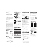
The
following
illustration
shows
the
connectors
and
LEDs
on
the
rear
of
the
server.
SP serial
System serial
Keyboard
Mouse
SP Ethernet 10/100
Gigabit Ethernet 2
Gigabit Ethernet 1
USB 1
USB 2
IXA RS485
Power-supply
Video
SP Ethernet
10/100 activity LED
Gigabit Ethernet 2
activity LED
Gigabit Ethernet 1
activity LED
Gigabit Ethernet 2
link LED
Gigabit Ethernet 1
link LED
SP Ethernet
10/100 link LED
I/O board error LED
Remote Supervisor Adapter II
SlimLine error LED
AC power
LED
DC power
LED
Fan error
LED
Power-supply
connector:
Connect
the
power
cord
to
this
connector.
Video
connector:
Connect
a
monitor
to
this
connector.
USB
1
connector:
Connect
a
USB
device
to
this
connector.
SP
Ethernet
10/100
connector:
Use
this
connector
to
connect
the
service
processor
to
a
network.
SP
Ethernet
10/100
activity
LED:
This
LED
is
on
the
SP
Ethernet
10/100
connector.
When
this
LED
is
lit,
it
indicates
that
there
is
activity
between
the
server
and
the
network.
SP
Ethernet
10/100
link
LED:
This
LED
is
on
the
SP
Ethernet
10/100
connector.
When
this
LED
is
lit,
it
indicates
that
there
is
an
active
connection
on
the
Ethernet
port.
USB
2
connector:
Connect
a
USB
device
to
this
connector.
6
IBM
System
x3800
Type
8865:
Problem
Determination
and
Service
Guide
Содержание x3800 - System - 8865
Страница 1: ...IBM System x3800 Type 8865 Problem Determination and Service Guide...
Страница 2: ......
Страница 3: ...IBM System x3800 Type 8865 Problem Determination and Service Guide...
Страница 8: ...vi IBM System x3800 Type 8865 Problem Determination and Service Guide...
Страница 28: ...12 IBM System x3800 Type 8865 Problem Determination and Service Guide...
Страница 122: ...106 IBM System x3800 Type 8865 Problem Determination and Service Guide...
Страница 130: ...114 IBM System x3800 Type 8865 Problem Determination and Service Guide...
Страница 182: ...166 IBM System x3800 Type 8865 Problem Determination and Service Guide...
Страница 195: ......
Страница 196: ...Part Number 31R1860 Printed in USA 1P P N 31R1860...