Before you begin
Power off the system and place it in the service position. For instructions, see “Preparing the 8001-12C or
8005-12N system to remove and replace internal parts” on page 85.
About this task
See “PCIe adapter placement rules and slot priorities for the 8001-12C or 8005-12N system” on page 23
for information and capabilities of the PCIe slots.
Attention:
For safety and airflow purposes, if you remove parts from the system, you must ensure that:
v
PCIe tail-stock fillers are present
v
System processor airflow baffles are present.
Procedure
1.
Attach the electrostatic discharge (ESD) wrist strap.
Attention:
v
Attach an electrostatic discharge (ESD) wrist strap to the front ESD jack, to the rear ESD jack, or to
an unpainted metal surface of your hardware to prevent the electrostatic discharge from damaging
your hardware.
v
When you use an ESD wrist strap, follow all electrical safety procedures. An ESD wrist strap is
used for static control. It does not increase or decrease your risk of receiving electric shock when
using or working on electrical equipment.
v
If you do not have an ESD wrist strap, just prior to removing the product from ESD packaging and
installing or replacing hardware, touch an unpainted metal surface of the system for a minimum of
5 seconds.
2.
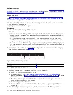
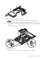
An adapter can share a PCIe riser card with other adapters. Label and remove any cables and plugs
that extend out of the adapters. See Figure 44.
Position
Step
2 (UIO Slot1)
3, 4, 5 (PLX Slot1, WIO Slot1, WIO Slot2)
3.
If you are working with a PCIe adapter in position 2, do the following:
a.
Remove the standard tailstock from the adapter.
b.
If you are inserting a storage drive adapter, connect the signal cables to the adapter before
inserting the adapter. See “Drive installation details for the 8001-12C system” on page 8 for cabling
information.
c.
If needed, install a support bracket for the PCIe adapter to the system backplane. Also install a
special support tailstock to the PCIe adapter.
d.
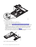
Insert the adapter into the PCIe riser.
e.
If you installed the support bracket for the PCIe adapter, fasten the special support tailstock to
that bracket.
4.
If the PCIe adapter to install is in positions 3, 4, or 5, you must remove the PCIe cage and riser.
Figure 44. 8001-12C PCIe adapter positions
76
Power Systems: Installing the IBM Power System S821LC (8001-12C)
Содержание Power System S821LC
Страница 1: ...Power Systems Installing the IBM Power System S821LC 8001 12C IBM...
Страница 2: ......
Страница 3: ...Power Systems Installing the IBM Power System S821LC 8001 12C IBM...
Страница 16: ...xiv Power Systems Installing the IBM Power System S821LC 8001 12C...
Страница 117: ...Figure 62 Connecting the power cords to the system Installing and configuring the system 101...
Страница 118: ...102 Power Systems Installing the IBM Power System S821LC 8001 12C...
Страница 130: ...114 Power Systems Installing the IBM Power System S821LC 8001 12C...
Страница 131: ......
Страница 132: ...IBM Printed in USA...


