2.
Beginning with the hole identified by mark
A
, count up one hole and place a second mark
B
. Mark
the rack so the mark can also be seen from the rear of the rack, as shown in Figure 2.
3.
Beginning with the hole identified by mark
B
, count up two holes and place a third mark
C
, as
shown in Figure 2.
4.
Facing the front of the rack and working from the left side, locate the bottom EIA unit that your
expansion unit uses. Mark the bottom hole of this EIA unit as
A
.
5.
Repeat steps 2 - 3 on the left side of the rack.
6.
Facing the rear of the rack and working from the right side, locate the bottom EIA unit that you noted
in step 1 on page 4. Make a mark next to the bottom hole of this EIA unit as
A
. Mark the rack so the
mark can also be seen from the front of the rack.
7.
Beginning with the hole identified by mark
A
, count up two holes and place a second mark
B
, as
shown in Figure 2.
8.
Facing the rear of the rack and working from the left side, locate the bottom EIA unit that your
expansion unit uses. Mark the bottom hole of this EIA unit as
A
.
9.
Repeat step 7 on the left side of the rack.
Attaching the 8231-E1C or 8231-E2C mounting hardware to the rack
You might need to attach the mounting hardware to the rack. Use the procedure in this section to
perform this task. This section also includes illustrations of the related hardware components and shows
how these components relate to each other.
Attention:
To avoid rail failure and potential danger to yourself and to the unit, ensure that you have
the correct rails and fittings for your rack. If your rack has square support flange holes or screw-thread
support flange holes, ensure that the rails and fittings match the support flange holes used on your rack.
Do not install mismatched hardware using washers or spacers. If you do not have the correct rails and
fittings for your rack, contact your IBM reseller.
To install the rack-mounting hardware into the rack, complete the following steps:
1.
Each slide rail is marked with either an R (right) or an L (left). Select the left slide rail, bring it to the
rear of the rack, and locate the selected U that was previously marked.
2.
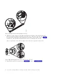
Push up on the front locking tab
(1)
, and pull out the front latch
(2)
at the front of the rail. Then
remove the screw from the rear of the rail
(3)
, as shown in Figure 3 on page 6.
Figure 2. Marking holes on the front and rear of the rack frame
Installing the server into a rack
5
Содержание POWER 730
Страница 2: ......
Страница 6: ...iv Power Systems Installing the IBM Power 710 Express 8231 E1C or IBM Power 730 Express 8231 E2C...
Страница 36: ...24 Power Systems Installing the IBM Power 710 Express 8231 E1C or IBM Power 730 Express 8231 E2C...
Страница 57: ......
Страница 58: ...Part Number 00L5066 Printed in USA GI11 9861 03 1P P N 00L5066...


