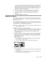


Preinstallation steps
Some of these steps are required only the first time you install a hard disk drive in a
specific bay.
1. Review the “Important safety information” on page iii, “Installation guidelines” on
page 35, and the documentation that comes with your drive.
2. Verify that you have all the cables and other equipment specified in the
documentation that comes with the drive.
3. Choose the bay in which you want to install the drive.
4. Check the instructions that come with the drive to see if you need to set any
switches or jumpers on the drive. If you are installing a SCSI device, be sure to
set the SCSI ID for that device.
Installing a drive in bay 2 or 4
Complete the following steps to install a drive in bay 2 or 4:
1. Follow the instructions in “Preinstallation steps” on page 47.
2. Turn off the computer and all attached devices.
3. Disconnect all external cables and power cords; then, remove the side cover
(see “Removing the side cover” on page 41).
4. Remove the support bracket (see “Removing and installing the support
bracket” on page 41).
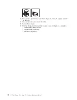
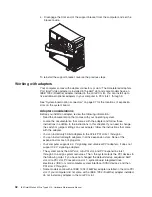
5. Use a screwdriver to pry the filler panel and EMC shield away from the
computer.
Note:
If you are installing a drive that contains a laser, observe the following
safety precaution.
Statement 3
CAUTION:
When laser products (such as CD-ROMs, DVD drives, fiber optic devices, or
transmitters) are installed, note the following:
v
Do not remove the covers. Removing the covers of the laser product could result in
exposure to hazardous laser radiation. There are no serviceable parts inside the
device.
v
Use of controls or adjustments or performance of procedures other than those
specified herein might result in hazardous radiation exposure.
Danger
Some laser products contain an embedded Class 3A or Class 3B laser diode. Note the
following. Laser radiation when open. Do not stare into the beam, do not view directly with
optical instruments, and avoid direct exposure to the beam.
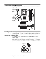
Installing options
47
Содержание 6219 - IntelliStation M - Pro
Страница 1: ...IBM IntelliStation M Pro Type 6219 Hardware Maintenance Manual...
Страница 2: ......
Страница 3: ...IBM IntelliStation M Pro Type 6219 Hardware Maintenance Manual...
Страница 6: ...iv IBM IntelliStation M Pro Type 6219 Hardware Maintenance Manual...
Страница 10: ...viii IBM IntelliStation M Pro Type 6219 Hardware Maintenance Manual...
Страница 26: ...16 IBM IntelliStation M Pro Type 6219 Hardware Maintenance Manual...
Страница 70: ...60 IBM IntelliStation M Pro Type 6219 Hardware Maintenance Manual...
Страница 88: ...78 IBM IntelliStation M Pro Type 6219 Hardware Maintenance Manual...
Страница 110: ...100 IBM IntelliStation M Pro Type 6219 Hardware Maintenance Manual...
Страница 127: ...Related service information 117...
Страница 128: ...118 IBM IntelliStation M Pro Type 6219 Hardware Maintenance Manual...
Страница 129: ...Related service information 119...
Страница 130: ...120 IBM IntelliStation M Pro Type 6219 Hardware Maintenance Manual...
Страница 131: ...Related service information 121...
Страница 132: ...122 IBM IntelliStation M Pro Type 6219 Hardware Maintenance Manual...
Страница 133: ...Related service information 123...
Страница 143: ...Related service information 133...
Страница 144: ...134 IBM IntelliStation M Pro Type 6219 Hardware Maintenance Manual...
Страница 152: ...142 IBM IntelliStation M Pro Type 6219 Hardware Maintenance Manual...
Страница 153: ......
Страница 154: ...Part Number 71P9918 1P P N 71P9918...


