Fuel System 110 Diesel Control System
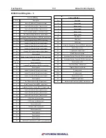
ECM Circuit Diagram – 3
Pin
Description
1
Injector (Cylinder #2) [Low]control output
2
Injector (Cylinder #4) [Low] control output
3
Injector (Cylinder #6) [Low] control output
4
Fuel Pressure Regulator Valve control output
5
Rail Pressure Regulator Valve control output
7
Intake Air Temperature Sensor (IATS) #2 signal input
10
Fuel Temperature Sensor (FTS) signal input
16
Injector (Cylinder #2) [High] control output
17
Injector (Cylinder #4) [High] control output
18
Injector (Cylinder #6) [High] control output
20
Electric VGT Control Actuator control output
21
Sensor ground
22
Engine Coolant Temperature Sensor(ECTS) signal input
23
Sensor ground
26,27
Sensor power (+5V)
28
Camshaft Position Sensor(CMPS) signal input
29
Sensor ground
31
Injector (Cylinder #1) [High] control output
32
Injector (Cylinder #3) [High] control output
33
Injector (Cylinder #5) [High] control output
39
Sensor ground
40
Rail Pressure Sensor(RPS) signal input
41
Boost Pressure Sensor(BPS) signal input
43
Crankshaft Position Sensor (CKPS) [-] signal input
46
Injector (Cylinder #1) [Low] control output
47
Injector (Cylinder #3) [Low] control output
48
Injector (Cylinder #5) [Low] control output
49
VSA motor [+] control output
50
VSA motor [-] control output
51
Sensor power (+5V)
52
Position Sensor signal input
54
Sensor power (+5V)
55
Sensor ground
56
Sensor ground
57
Sensor shield
58
Crankshaft Position Sensor (CKPS) [+] signal input
Connector
[ECU-A]
Pin
Description
1,2
Power ground
3
Battery power
4
Power ground
5
Battery power
6
Battery power
18
Key power
35
CAN [Low]
36
CAN [High]
38
Intake Air Temperature Sensor (IATS) #1 signal input
42
Sensor Power (+5V)
47
Engine speed signal output
49
Main Relay control output
57
Accelerator Position Sensor (APS) #1 signal input
58
Accelerator Position Sensor (APS) #2 signal input
60
Sensor power (+5V)
68
Fuel Pump Relay control output
72
Diagnosis Data Line (K-Line)
79
Sensor ground
80,81
Sensor ground
82
Sensor power (+5V)
90
Feedback signal input
91
Malfunction Indicator Lamp (MIL) Control output
Connector
[ECU-K]
Содержание S220P
Страница 3: ...Engine Mechanical System 2 General Information General Information Specifications ...
Страница 4: ...Engine Mechanical System 3 General Information Specifications ...
Страница 5: ...Engine Mechanical System 4 General Information Specifications ...
Страница 10: ...Engine Mechanical System 9 Cooling System Special Service Tools ...
Страница 11: ...Engine Mechanical System 10 Cooling System Special Service Tools ...
Страница 18: ...Engine Mechanical System 17 Cooling System ...
Страница 19: ...Engine Mechanical System 18 Cooling System Thermostat ...
Страница 55: ...Engine Mechanical System 54 Lubrication System ...
Страница 73: ...Engine Electrical System 72 General Information Troubleshooting Charging system ...
Страница 74: ...Engine Electrical System 73 General Information Starting system Special service tools ...
Страница 75: ...Engine Electrical System 74 Charging System Charging system Alternator ...
Страница 80: ...Engine Electrical System 79 Starting System Components ...
Страница 91: ...Fuel System 90 General Information Special Service Tools ...
Страница 112: ...Fuel System 111 Diesel Control System EOI Engine Operating Indicator System Circuit Diagram 1 ...
Страница 117: ...Fuel System 116 Diesel Control System Specification Circuit Diagram ...


