


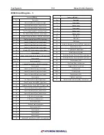


Fuel System 107 Diesel Control System
57
Accelerator Position Sensor (APS) #1
signal input
ON
DC
0.7 ~ 0.8V
Idle
3.8 ~ 4.4V
58
Accelerator Position Sensor (APS) #2
signal input
WOT
DC
0.275 ~ 0.475V
Idle
1.75 ~ 2.35V
60
Sensor power (+5V)
IG ON
DC
4.9 ~ 5.1V
68
Fuel Pump Relay control output
OFF / ON
DC
Battery Voltage / Max 1.0 V
72
Diagnosis Data Line (K-Line)
When
transmitting
Pulse
High: Min. V batt x 80%
Low: Max. V batt x 20%
When
receiving
High: Min. V batt× 70%
Low: Max. V batt× 30%
79
Sensor ground
Always
DC
0 ~ 0.5V
80
Sensor ground
Always
DC
0 ~ 0.5V
81
Sensor ground
Always
DC
0 ~ 0.5V
82
Sensor power (+5V)
IG ON
DC
4.9 ~ 5.1V
90
EVGT feedback signal input
IG ON
PWM
Engine running duty: 20~8
91
Malfunction Indicator Lamp (MIL) Control
output
OFF
DC
Battery Voltage
ON
Max 1.0 V
ECM Replacement
1. Turn ignition switch OFF and disconnect the negative
(-) battery cable. .
2. Remove the cover of the ECM & relay box
3. Disconnect the ECM connector
4. Install a new ECM.
ECM Problem Inspection Procedure
1. TEST ECM GROUND CIRCUIT: Measure resistance
between ECM and chassis ground using the backside
of ECM harness connector as ECM side check point. If
the problem is found, repair it.
2. TEST ECM CONNECTOR: Disconnect the ECM
connector and visually check the ground terminals on
ECM side and harness side for bent pins or poor
contact pressure. If the problem is found, repair it.
3. If problem is not found in Step 1 and 2, the ECM
could be faulty. If so, replace the ECM with a new
one, and then check the engine again. If the engine
operates normally then the problem was likely with
the ECM.
4. RE-TEST THE ORIGINAL ECM : Install the original
ECM (may be broken) into a known-good engine and
check the engine. If the problem occurs again, replace
the original ECM with a new one. If problem
does not occur, this is intermittent problem (Refer to
INTERMITTENT PROBLEM PROCEDURE in BASIC
INSPECTION PROCEDURE)
Содержание S220P
Страница 3: ...Engine Mechanical System 2 General Information General Information Specifications ...
Страница 4: ...Engine Mechanical System 3 General Information Specifications ...
Страница 5: ...Engine Mechanical System 4 General Information Specifications ...
Страница 10: ...Engine Mechanical System 9 Cooling System Special Service Tools ...
Страница 11: ...Engine Mechanical System 10 Cooling System Special Service Tools ...
Страница 18: ...Engine Mechanical System 17 Cooling System ...
Страница 19: ...Engine Mechanical System 18 Cooling System Thermostat ...
Страница 55: ...Engine Mechanical System 54 Lubrication System ...
Страница 73: ...Engine Electrical System 72 General Information Troubleshooting Charging system ...
Страница 74: ...Engine Electrical System 73 General Information Starting system Special service tools ...
Страница 75: ...Engine Electrical System 74 Charging System Charging system Alternator ...
Страница 80: ...Engine Electrical System 79 Starting System Components ...
Страница 91: ...Fuel System 90 General Information Special Service Tools ...
Страница 112: ...Fuel System 111 Diesel Control System EOI Engine Operating Indicator System Circuit Diagram 1 ...
Страница 117: ...Fuel System 116 Diesel Control System Specification Circuit Diagram ...