


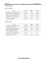


Fuel System 93 General Information
Basic Inspection Procedure
The measured resistance at high temperature after
vehicle running may be high or low. So all resistance
must be measured at ambient temperature (20
℃
, 68
℉
),
unless stated otherwise.
✍
NOTICE
The measured resistance in except for ambient
temperature (20
℃
, 68
℉
) is reference value.
Sometimes the most difficult case in troubleshooting is
when a problem symptom occurs but does not occur
again during testing.
An example would be if a problem appears only when
the engine is cold but has not appeared when warm. In
this case, the technician should thoroughly make out a
"CUSTOMER PROBLEM ANALYSIS SHEET" and
recreate (simulate) the environment and condition
which occurred when the vehicle was having the issue.
1. Clear Diagnostic Trouble Code (DTC).
2. Inspect connector connection, and check terminal
for poor connections, loose wires, bent, broken or
corroded pins, and then verify that the connectors are
always securely fastened
3. Slightly shake the connector and wiring harness
vertically and horizontally.
4. Repair or replace the component that has a problem.
5. Verify that the problem has disappeared with the
road test
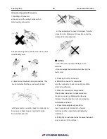
●
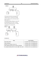
Simulating Vibration
a. Sensors and Actuators
: Slightly vibrate sensors, actuators or relays with
finger
☢
WARNING
Strong vibration may break sensors, actuators or
relays
b. Connectors and Harness
: Lightly shake the connector and wiring harness
vertically and then horizontally
.
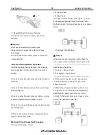
●
Simulating Heat
a. Heat components suspected of causing the
malfunction with a hair dryer or other heat source
☢
WARNING
• DO NOT heat components to the point where
they may be damaged.
• DO NOT heat the ECM directly
● Simulating Water Sprinkling
a. Sprinkle water onto engine to simulate a rainy day or
a high humidity condition
☢
WARNING
DO NOT sprinkle water directly into the engine
compartment or electronic components.
● Simulating Electrical Load
.
a. Turn on all electrical systems to simulate excessive
electrical loads (Radios, fans, lights, rear window
defogger, etc.).
Содержание S220P
Страница 3: ...Engine Mechanical System 2 General Information General Information Specifications ...
Страница 4: ...Engine Mechanical System 3 General Information Specifications ...
Страница 5: ...Engine Mechanical System 4 General Information Specifications ...
Страница 10: ...Engine Mechanical System 9 Cooling System Special Service Tools ...
Страница 11: ...Engine Mechanical System 10 Cooling System Special Service Tools ...
Страница 18: ...Engine Mechanical System 17 Cooling System ...
Страница 19: ...Engine Mechanical System 18 Cooling System Thermostat ...
Страница 55: ...Engine Mechanical System 54 Lubrication System ...
Страница 73: ...Engine Electrical System 72 General Information Troubleshooting Charging system ...
Страница 74: ...Engine Electrical System 73 General Information Starting system Special service tools ...
Страница 75: ...Engine Electrical System 74 Charging System Charging system Alternator ...
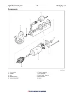
Страница 80: ...Engine Electrical System 79 Starting System Components ...
Страница 91: ...Fuel System 90 General Information Special Service Tools ...
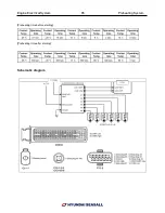
Страница 112: ...Fuel System 111 Diesel Control System EOI Engine Operating Indicator System Circuit Diagram 1 ...
Страница 117: ...Fuel System 116 Diesel Control System Specification Circuit Diagram ...