- 4 -
INLET ADAPTER VALVE INSTALLATION
NOTE:
This assembly is offered as an optional installation method. Make sure it is approved for use under State
and local plumbing codes before ordering kit (P/N 42500004).
NOTE:
Use this assembly on U.S.N.P.T.* pipe thread fittings only.
CAUTION:
DO NOT INSTALL FEED WATER ASSEMBLY ON HOT WATER LINE.
1. Locate shut off valves on water lines under sink. To
identify hot supply pipe and cold supply pipe, turn
both faucets on and let water run. As water flows,
hot water pipe becomes noticeably warmer.
2. Turn off cold water supply by closing shut off valve.
Drain line by opening sink faucet. Some mixing type
faucets may also require turning off hot water supply.
NOTE:
If no shut off valve is installed under sink, close
main water valve during this installation.
Place a container or towel below shut-off valve to
catch any water remaining in pipe.
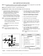
All item callouts refer to Figure 4 unless noted
otherwise.
3. Disconnect cold water supply line to sink at inlet
valve end of line.
NOTE:
Use Teflon tape (P/N 35700002) on male
threaded connections in Steps 4, 6, 7, and 8.
EXISTING COLD WATER
SUPPLY VALVE
COLD WATER LINE
TO SINK
4. Insert rubber washer (Item 1) into inlet adapter (Item
2) and install adapter onto supply valve. Align outlet
hole (in side of adapter) toward Filtration Module.
5. Replace existing rubber grommet on cold water
supply line with grommet supplied in kit (Item 3).
6. Attach cold water supply line to inlet adapter.
7. Install ball valve (Item 4) into inlet adapter.
8. Install male connector (Item 5) into inlet ball valve.
9. Install ¼” white tubing (Item 6) from male connector
to Filtration Module inlet elbow (Item 8 on Page 10,
Figure 10).
10. Close inlet valve by turning handle so it is at a right
angle (90º) to valve body.
11. Turn on cold water supply. Check installation for
leaks. Allow water to run from faucet for a few
minutes to clear any debris in the supply line caused
by this installation.
NOTE:
If flow from faucet is reduced, clean faucet
aerator.
Item
Description
Part No.
Inlet Assembly
1 Rubber
Washer
33400002
2
Inlet Adapter 1/2" x 1/
2
" x 1/8"
33201001
3 Rubber
Grommet
33400003
4
Inlet Ball Valve 1/8"
34900002
5
Male Connector 1/4" x 1/8" NPT*
33503301
Component of Installation Kit
6
Tubing, 1/4" White
20300014
* United States
National Pipe Thread
Figure 4
Inlet Adapter Assembly P/N 42500004 Installation and Parts Breakdown


