background image


INSTALLATION REQUIREMENTS


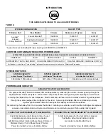
READ THIS ENTIRE INSTALLATION AND SERVICE GUIDE BEFORE BEGINNING INSTALLATION 

This Aquafier

®

 Drinking Water Treatment System is designed for ease of installation and serviceability. 

It is constructed with the finest materials available. 

Using these instructions and paying close attention to parameters outlined within  "CONDITIONS FOR USE" detailed 

on Page ii will ensure a successful installation. 


This system must be installed in accordance with applicable city, state, and local plumbing codes. 

To insure the system continues to operate at its optimum level, 

it is necessary to have a routine maintenance and replacement schedule (Page 11).   

The frequency at which filters need changing will depend on quality of feed water supply and level of system usage.


PREPARATION


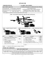
1.  Check that all appropriate components are packed 

with your system (Page II, Figure 1).  Refer to 
applicable Component Parts Breakdown (Figure 7, 9, 
or 10) for a complete list of its constituent parts. 


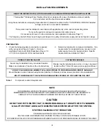
2.  Determine locations for component installation.  Two 

requirements for consideration are: access to cold 
water supply line and to household sink.  Specific 
requirements are detailed in Table 1. 


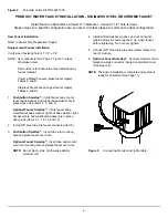
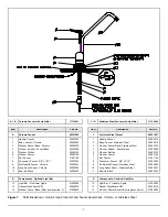
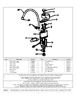
PRODUCT WATER FAUCET


FILTRATION MODULE


Faucet may be installed in any convenient location.   

Make sure underside of location is free of obstructions. 


Module may be installed under a sink or in any convenient 

location. within 15 feet of source water supply and faucet 

* DO NOT PLACE MODULE WHERE IT WILL BE EXPOSED TO FREEZING AND/OR DIRECT SUNLIGHT.


Mount Module on side of cabinet using bracket (attached to Module) and two screws provided in the Installation Kit. 

HOLD THE MODULE BY THE FILTER HOUSINGS WHEN PICKING UP OR CARRYING THE UNIT


Table 1 


Component Location Requirements 


NOTE


THIS DRINKING WATER SYSTEM IS FOR USE ON POTABLE WATER SUPPLIES ONLY.  

COMMONWEALTH OF MASSACHUSETTS PLUMBING CODES 248 CMR SHALL BE ADHERED TO. 

CONSULT WITH YOUR LICENSED PLUMBER FOR INSTALLATION OF THIS SYSTEM. 


CAUTION 

DO NOT USE WITH WATER THAT IS MICROBIOLOGICALLY UNSAFE OR OF UNKNOWN 

QUALITY WITHOUT ADEQUATE DISINFECTION BEFORE OR AFTER THE SYSTEM. 


SYSTEMS CLAIMING CYST REDUCTION


SYSTEMS CERTIFIED FOR CYST REDUCTION  

MAY BE USED ON DISINFECTED WATERS THATMAY CONTAIN FILTERABLE CYSTS. 

IF SIGNIFICANT INLET WATER PRESSURE DIFFERENTIALS OCCUR, PRESSURE REGULATOR MUST BE USED. 


 III

Содержание 10401

Страница 1: ...OWNER S GUIDE NSFR AQUAFIER ADVANCED ACTIVATED CARBON WATER TREATMENT SYSTEM Model Series 10401 10402 10403 Hydrotech Inc 25555 West Avenue Stanford Valencia CA 91355 661 294 8888 FAX 661 294 8880...

Страница 2: ...OR The optional Smartap Monitor indicates filter cartridge status by measuring the volume of water passing through the Aquafier Water Treatment System When water is dispensed it flows through the syst...

Страница 3: ...Quality Monitor Pushbutton Smartap Water Quality Monitor Module Only No Monitor Product Water Faucet Chrome or Stainless Steel Polymer Plain Front or with Light Bar Page I Table A Page 7 Fig 7 Page 9...

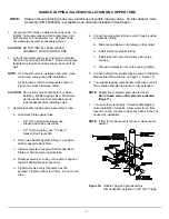
Страница 4: ...are access to cold water supply line and to household sink Specific requirements are detailed in Table 1 PRODUCT WATER FAUCET FILTRATION MODULE Faucet may be installed in any convenient location Make...

Страница 5: ...cause the tubing to flex and deform which reduces its flow capacity and may increase lateral stress on the fittings causing leaks QUICK CONNECT FITTINGS Fittings consist of two parts a Body and a colo...

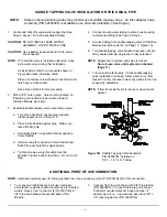
Страница 6: ...side projections 1 2 or larger tubing use V side of bracket See Figure 3B b Hold Valve Saddle against tubing in a position directly opposite Back Plate c Install screws far enough so Saddle and Back...

Страница 7: ...nst pipe e Tighten screws evenly brackets must be parallel Tighten each screw firmly Do not crush pipe 4 Connect source water tubing to valve housing using compression fitting See Page 2 Step 4 5 Conn...

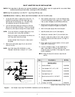
Страница 8: ...6 7 and 8 EXISTING COLD WATER SUPPLY VALVE COLD WATER LINE TO SINK 4 Insert rubber washer Item 1 into inlet adapter Item 2 and install adapter onto supply valve Align outlet hole in side of adapter t...

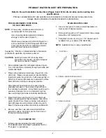
Страница 9: ...htly Insert pilot guide into pilot hole Push down gently on drill motor to apply light pressure to porcelain surface Start drill motor turning as slowly as possible After initial cut has started motor...

Страница 10: ...e washer are in place above sink Items 2 3 and 4 Optional Faucet Smartap Verify faucet body metal faucet base washer light bar base washer light bar assembly and washboard gasket are in place above si...

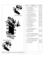
Страница 11: ...Handle Faucet Body Faucet Stainless Steel Washer Faucet Base Stainless Steel Washer Rubber Faucet Base Washer Slotted Washer Faucet Nut Faucet Connector Faucet 3 8 x 7 16 Kit Rebuild Faucet Stainless...

Страница 12: ...g nut by hand so that faucet does not move Do not over tighten NOTE Faucet is packaged for right hand operation For left hand operation realign knob by completing Step 5 NOTE Item callouts in Step 5 r...

Страница 13: ...designates faucet body with plain front Code 1 designates faucet body with 1 LED Code 2 designates faucet body with 2 LED Code 3 designates faucet body with 3 LED Example 40303935 is a Faucet Body Ass...

Страница 14: ...lel Cross over O Ring Port Retainer Plug Port Retainer Plug Switch Housing O Ring Switch Housing Plug O Ring Cartridge Activator Smartap Flow Monitor Sending Unit Flow Switch Spring Flow Switch Magnet...

Страница 15: ...Gap Faucet Part Number Stainless Steel Faucet Only Stainless Steel with Light Bar 40301007 11702002 Chrome Faucet Only Chrome with Light Bar 40301002 11702001 Polymer Plain Front Polymer Light Bar 114...

Страница 16: ...ACH WILL DAMAGE PLASTIC AND RUBBER COMPONENTS Rinse all parts that contact bleach thoroughly with clean potable water CAUTION Read the WARNINGS on the bleach container before using CAUTION Handle sani...

Страница 17: ...y The connection to the battery is a snap type connector See Figure 11 20 Remove the battery by sliding it out of its holder 21 Replace the battery with a new alkaline 9 volt transistor battery P N 31...

Страница 18: ...hes Lube and Reseat O Ring Replace O Ring Leak at saddle tapping valve Loose clamp Tubing deformed Tighten clamp screws do not crush source water tubing Cut damaged area off of tube or replace tube an...

Страница 19: ...D SERVICED BY COMPANY SERVICE PERFORMED CLEANING ONLY CLEANING SANITIZING REPAIR FILTERS REPLACED CARBON Pb1 LEAD CARBON 5s VOC s COMMENTS DATE SERVICED SERVICED BY COMPANY SERVICE PERFORMED CLEANING...

Страница 20: ...eet Hydrotech specifications If the drinking water system is altered by anyone other than Hydrotech the warranty shall be void ALL IMPLIED WARRANTIES INCLUDING WITHOUT LIMITATION WARRANTIES OF MERCHAN...

Отзывы: